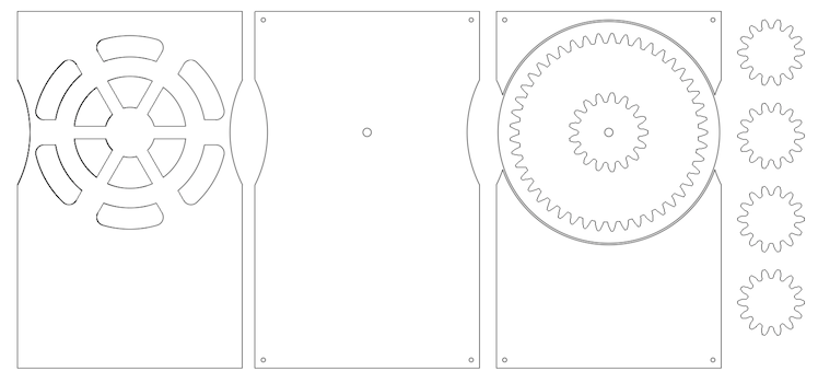
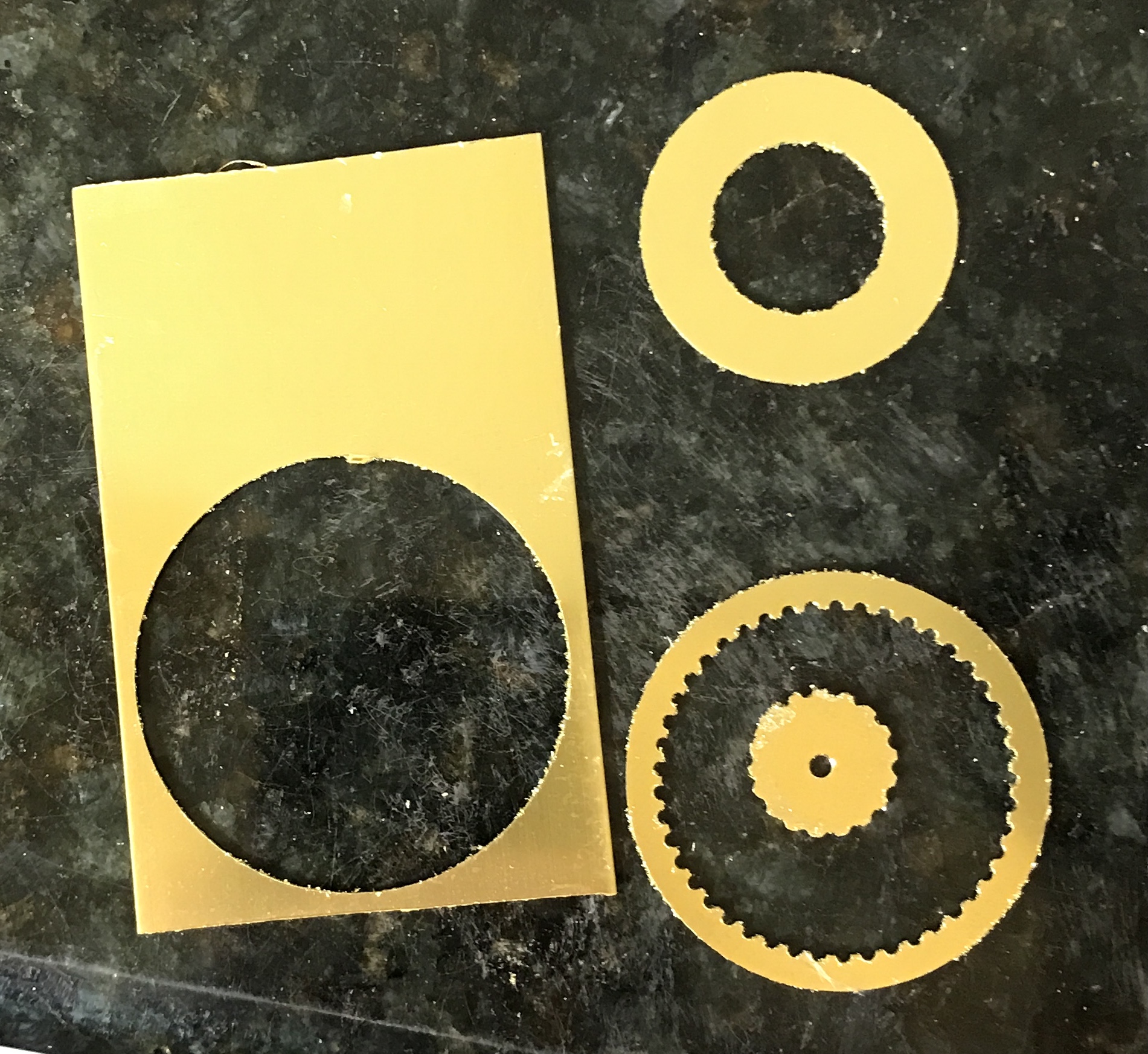
I have always been intrigued by a business card plan seen many years ago. I no longer know where it came from. It houses a set of planetary gears. I finally decided to make it. My first attempt is making it from brass stock that is 1/32" thick. I have 1/16" stock if this proves too thin. The parts seen in the plan below will be referred to (starting from the left) as front, back, and middle.
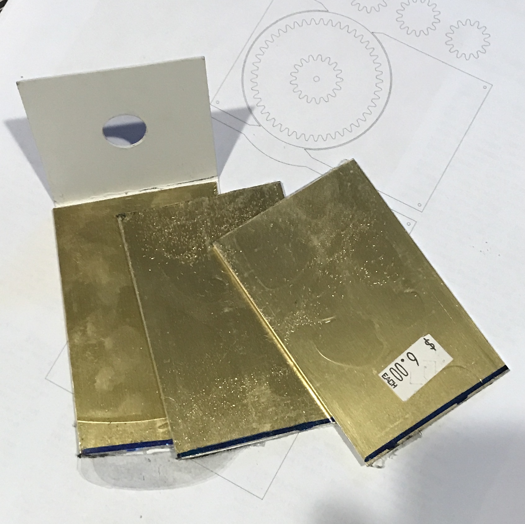
Some brass flat stock was found. It is 1/32" X 2" X 10". Three pieces were cut from this stock. Two, front and back, were slightly longer than 3" and one, the middle, slightly longer than 3 1/8". The middle part including the large internally toothed gear will be made by cutting out the gear on a rotary table. Using a 1/16" end mill requires the plate to be 1/8" longer for the waste. I plan to leave the cards oversize and cut them to size after clamping them together. The corner holes will also be drilled at this time.
The openings in the top card will also be cut on the rotary table. Cutting the gear teeth will initially be attempted by rough cutting on the scroll saw followed by hand filing. It is possible that the gear teeth on the five small gears could be cut with one of the gear cutters I already have.
The plan dimensions are as follows. The card is 1.844" X 2.938". The large wheel diameter is 1.813". The inner diameter of the large wheel is 1.469". The central wheel diameter is slightly less than 0.656". The planetary gears are 0.563" in diameter. Tooth length is 0.078". Tooth width is 0.063". The planetary gears have 14 teeth, the central gear has 17 teeth, and the large gear has 45 internal teeth.
The gear cutting parameters were calculated. Diametral Pitch = (# of teeth + 2)/O.D. The DP of the planetary and central gears are 28.4 and 28.9 respectively. The gear cutters I have are DP = 30. This would result in using smaller blanks for the two gear sizes: 0.533" and 0.633". The size of the outer wheel would have to expand accordingly. I don't know how to do this and determine the number of teeth for this newly sized gear. So either two gear cutters (6 & 7) need to be made or purchased. Alternatively, a hob might be the best way to go.
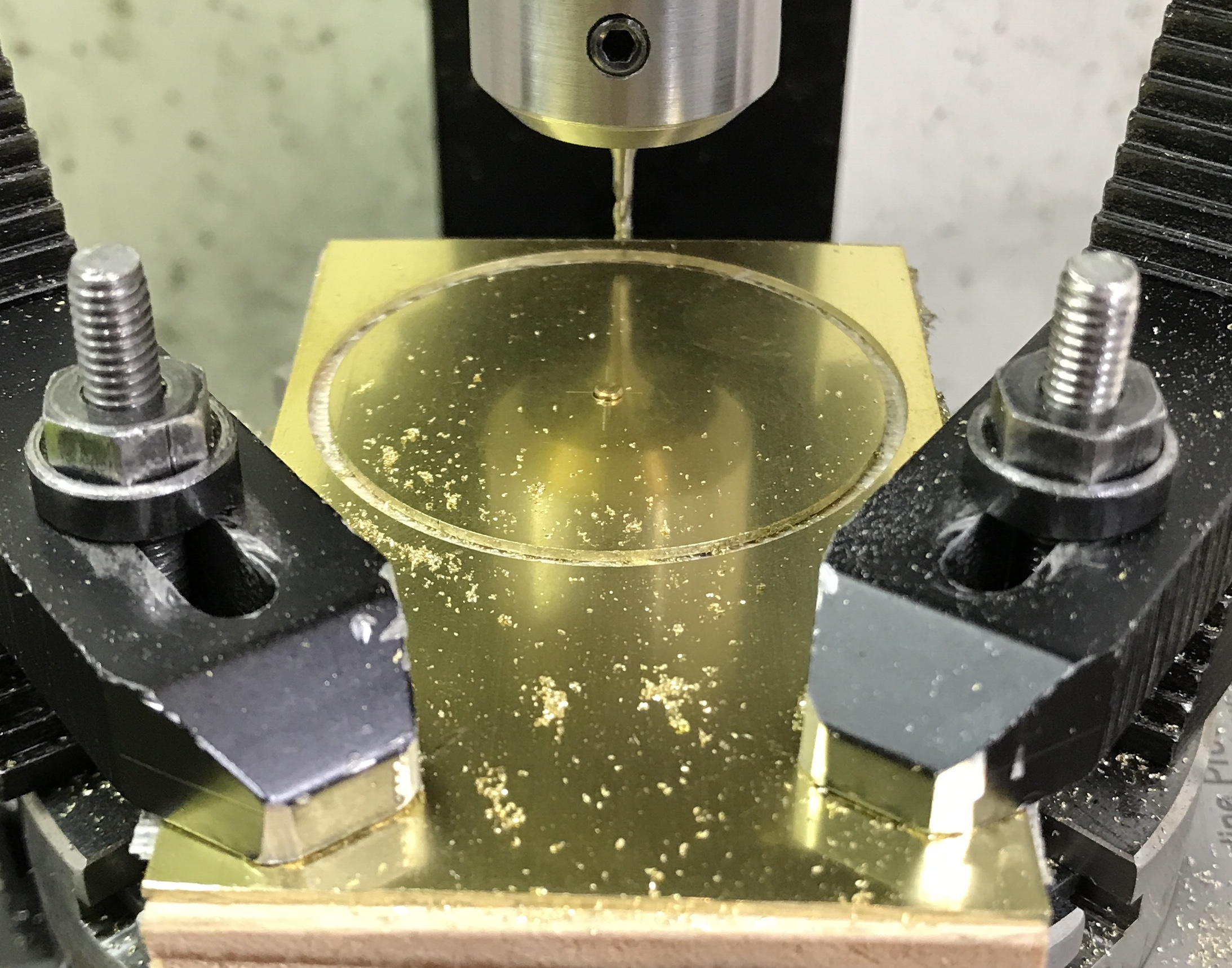
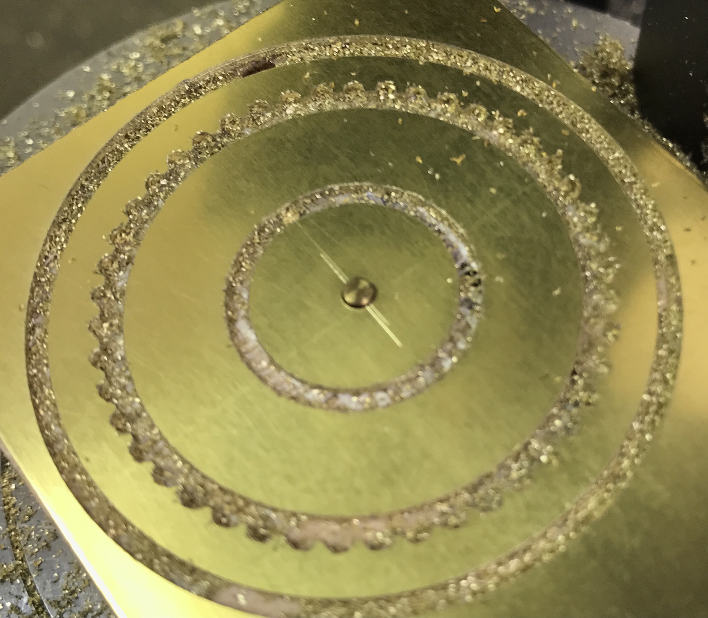
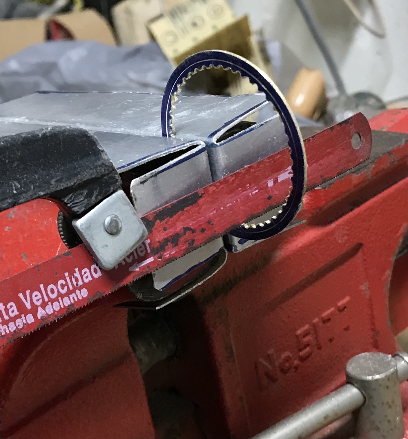
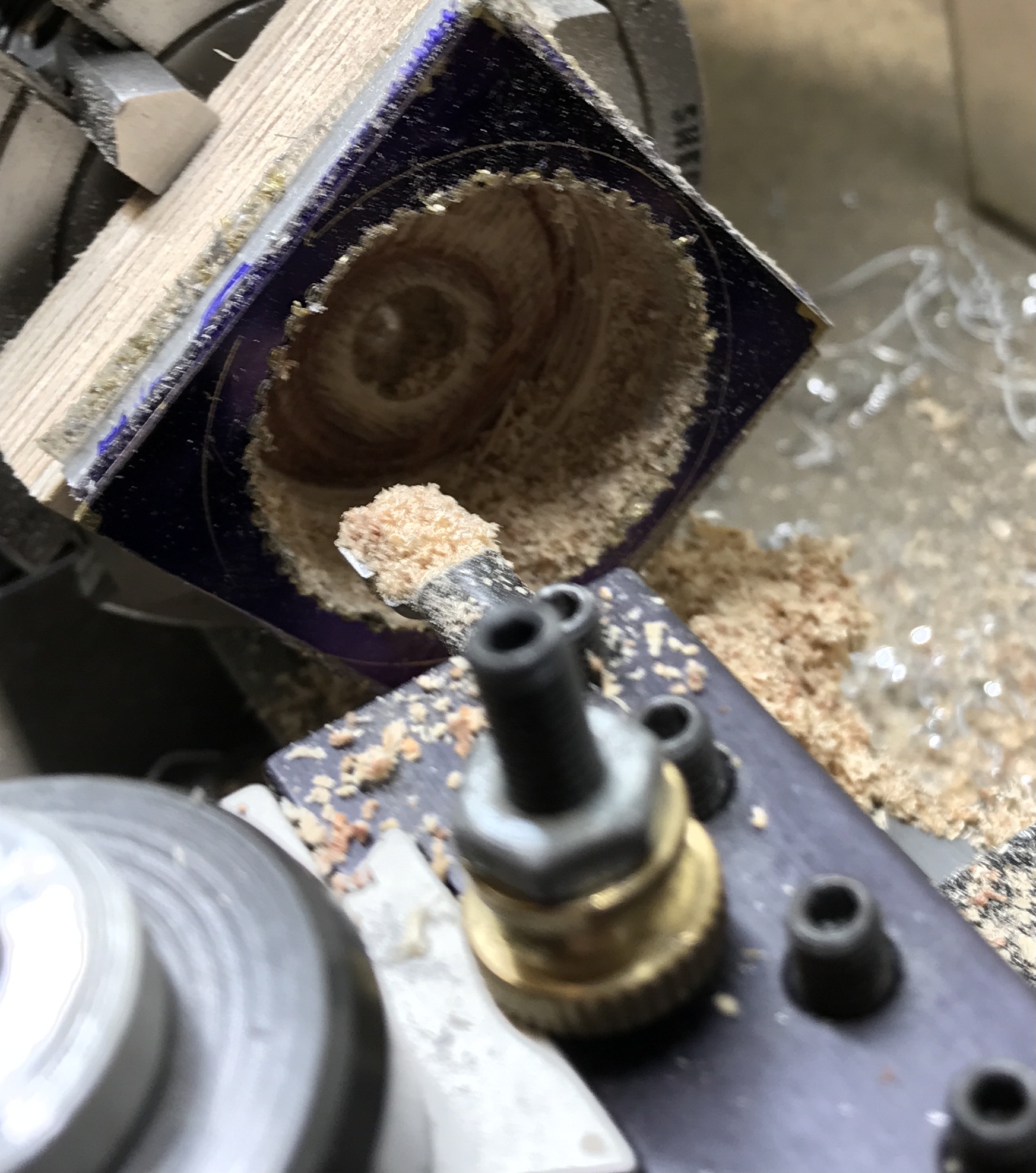
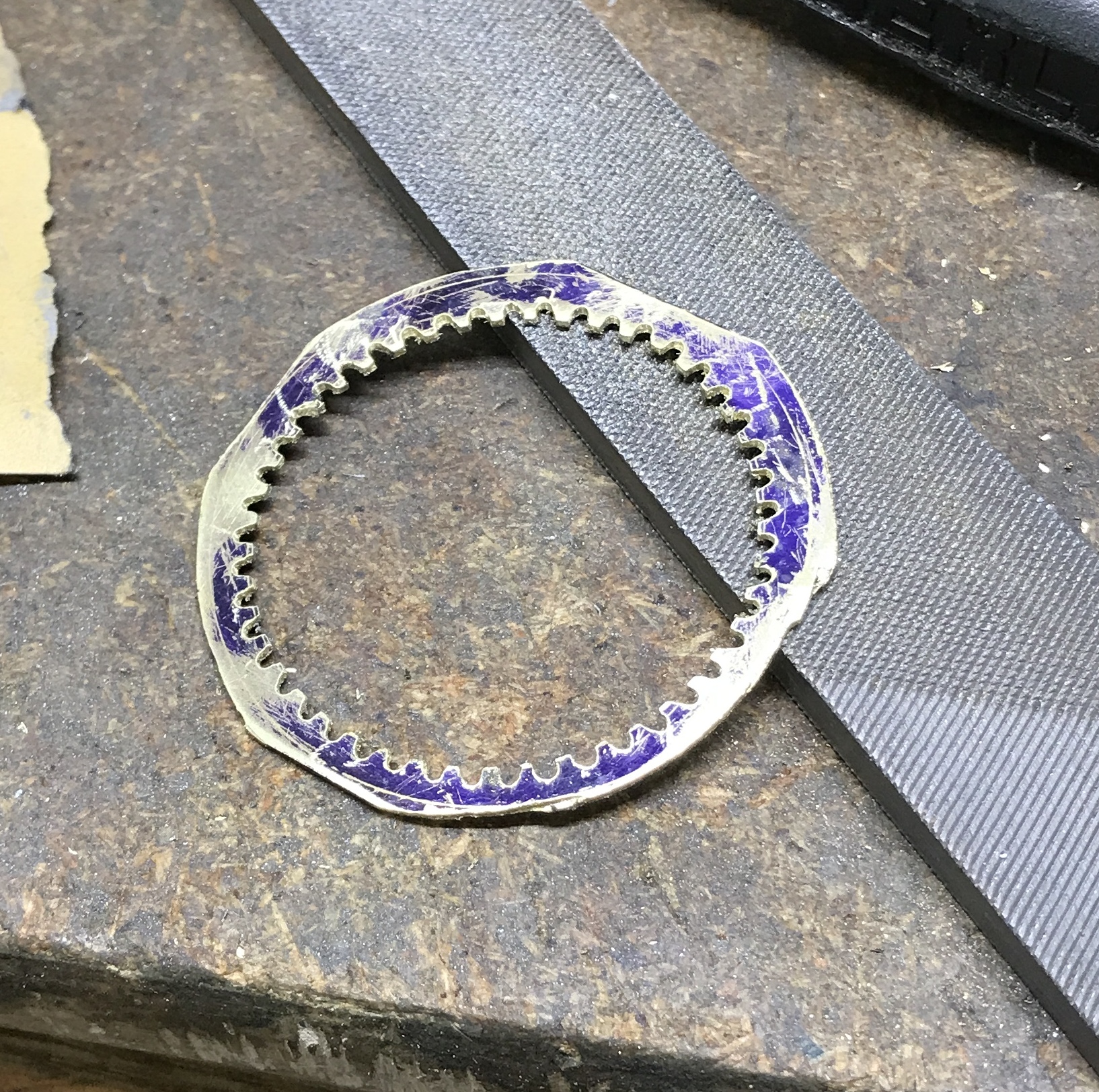
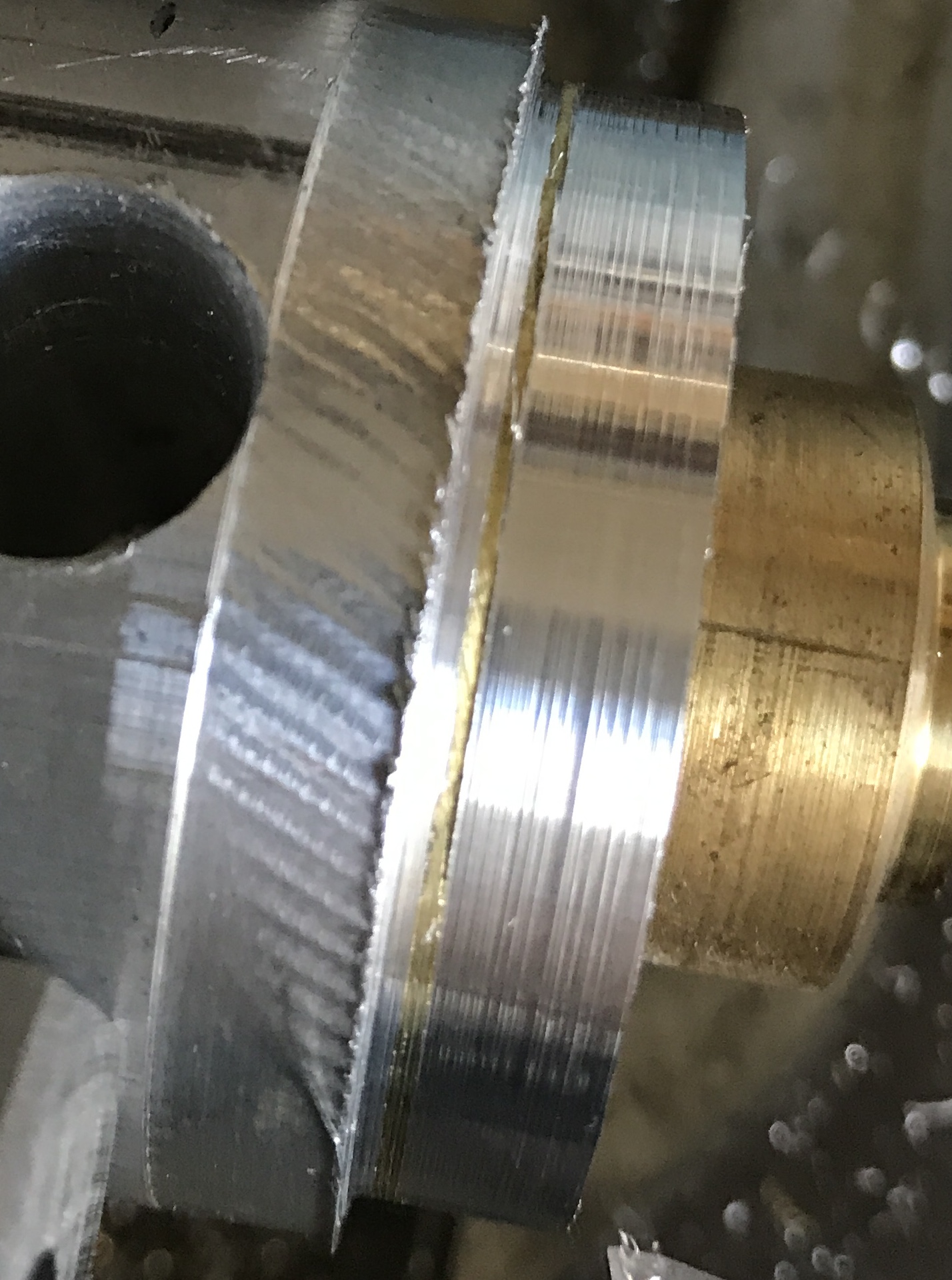
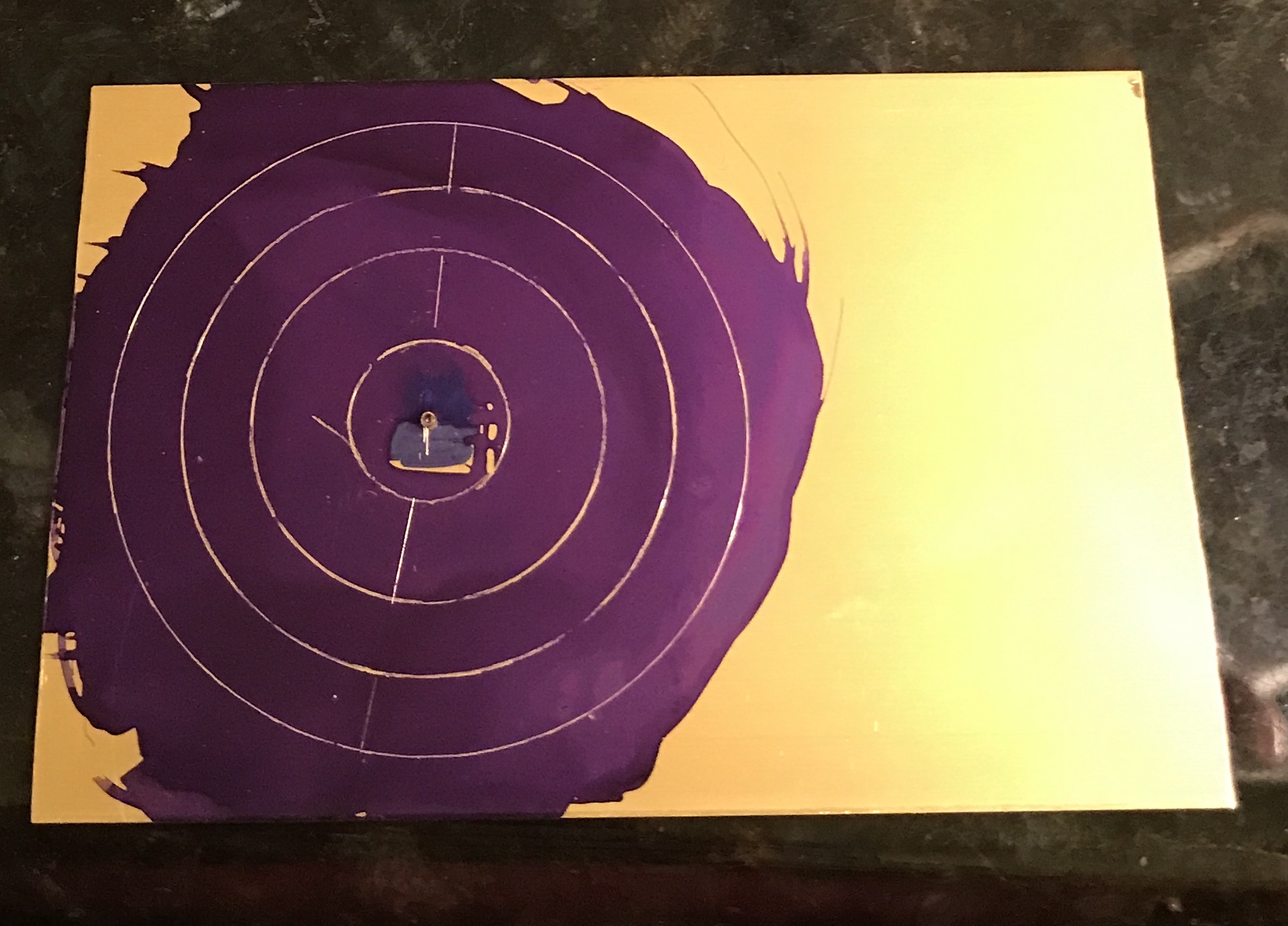
The middle part was marked for a center hole. A 0.089" (#43 drill) hole was drilled through after centering the spindle over the mark with the new slip-on spud. A 3/4" block of wood was cut to fit the part and marked for a hole. This hole was drilled through 7/16" in the drill press to fit the rotary table adaptor. Once the part was carpet taped to the block and clamped in place, the table was centered under the spindle. The table was moved 0.906" and locked on both axes. A 1/16" end mill was used to cut the circle in increments of 0.005". The picture shows the result.
Of course that was the wrong distance to move the table. It needed 1/32" less. This means the circle gear will have a slightly smaller O.D. This should not matter if the inner circle is cut to the correct size. Should have taken the time to do the layout.
The outside of the cutter is now 1/32" beyond the correct size of the wheel at 0.937". The outside of the cutter needs to be inside the inner circle to cut it correctly. The radius of the inner circle is 0.7345". So the part needs to move back 0.203" for the 1/16" end mill to cut the inner circle of the doughnut.
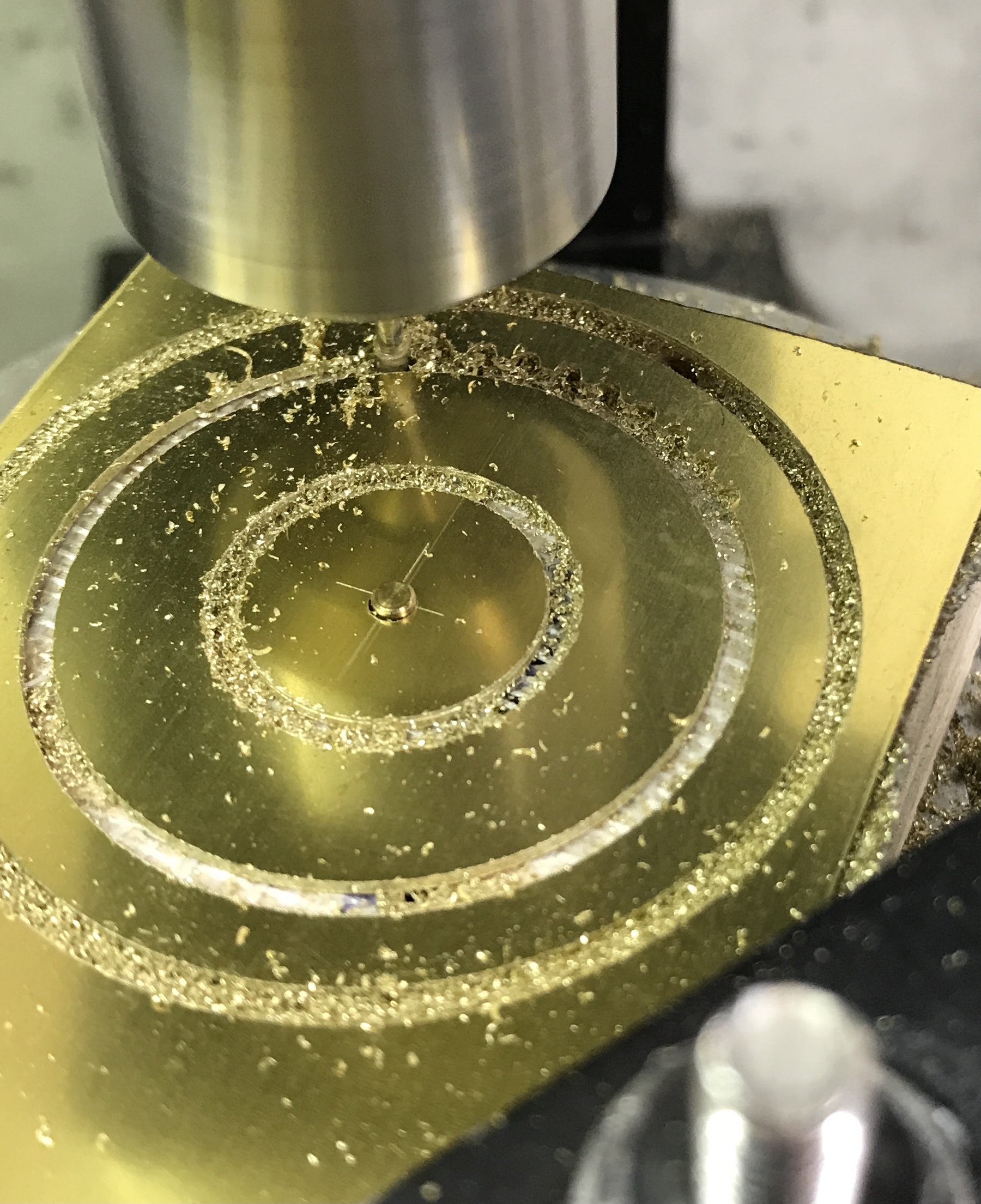
Change in plans. Instead of cutting out the large gear circle first, the inner gear will be removed first. That way one clamp setup will serve for both cuts. There is also more room for the clamps when cutting the inner gear. The inside of the end mill is sitting at 0.937" - 1/16" = 0.875". The inner gear is 0.641" in diameter. Consequently, the table needs to move back toward center 0.555". This was done and the inner gear circle was cut free.
Now the outside of the end mill is at 0.3205" + 1/16" = 0.383". The outside of the end mill needs to be at radius 0.735", so the table needs to move back out 0.352" to cut the inner side of the large gear wheel. Again the table was moved and the wheel was cut loose. The clamps were not moved for these last two cuts. The carpet tape was sufficient to hold everything tight for both cuts.
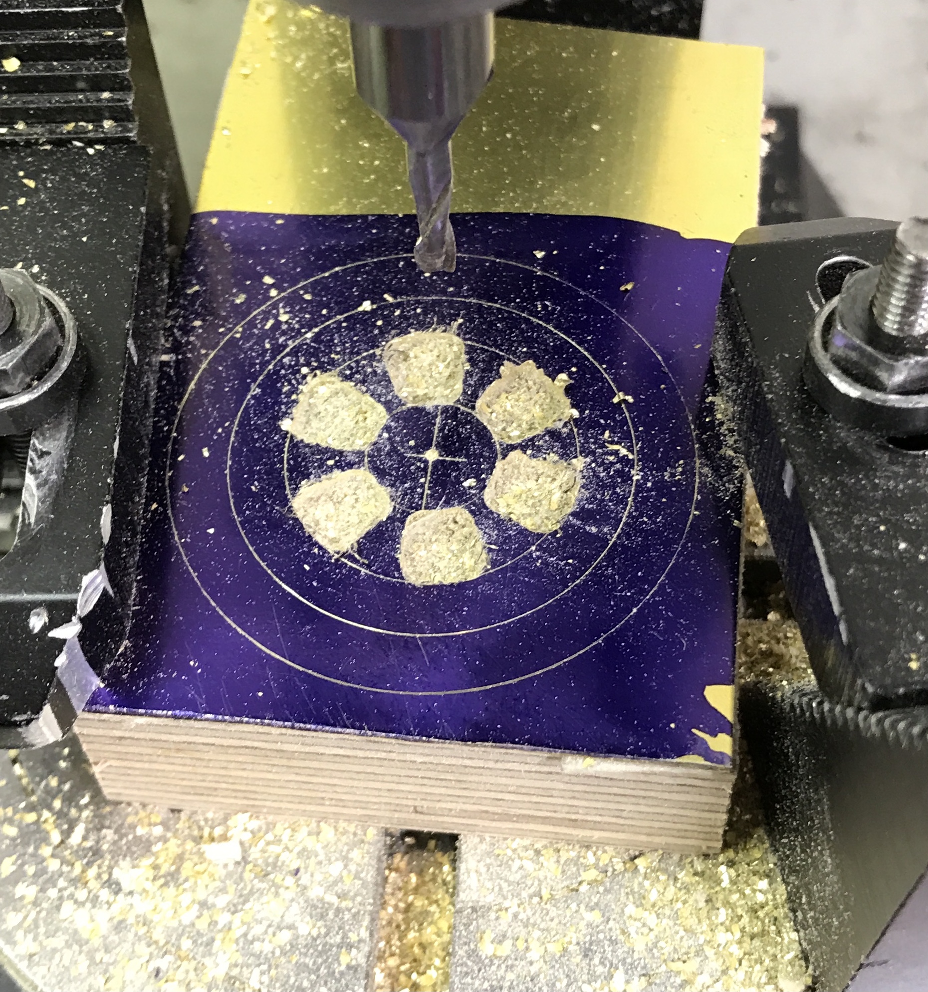
The width of the gap between the teeth of the large wheel is 1/16" at the inner diameter. The plan is to start the teeth with the end mill and finish with a file. The end mill from its current position can cut 1/32" deep into the circle to reveal the beginnings of the teeth. The wheel has 45 teeth. The teeth are 8° apart. The spindle was moved to about touching and the z-axis set to 0. The table was rotated until it was also at zero. With the x-axis locked the spindle was lowered 0.015" and the y-axis was moved 0.031". The table was lowered another 0.015" for a second cut and again for a third cut. Everything was returned to initial positions taking care to remove the backlash in both the y- and z-axes. The table was rotated 8° and the second gap between teeth was cut. After repeating this 43 more times the initial gaps were completed.
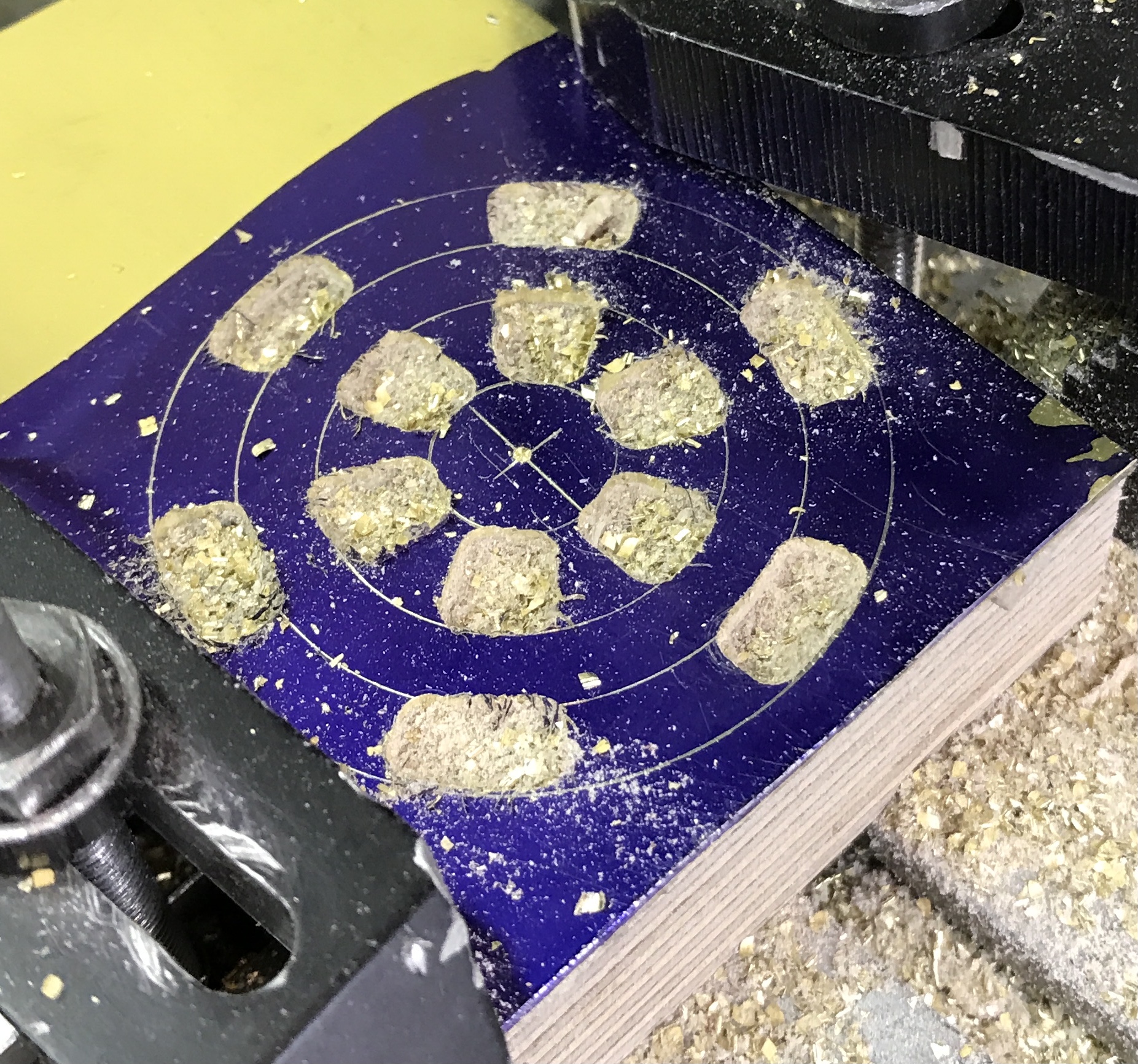
The same process was followed for the central gear with 17 teeth. The table was moved back 0.352" to place the edge of the cutter against the central gear. A spreadsheet was made to calculate the rotary table settings for each of the cuts. The seventeen cuts were made as above 1/32" into the wheel. The last few cuts were only partial as unbeknownst to me the gear came partly loose. They are sufficiently marked for filing.
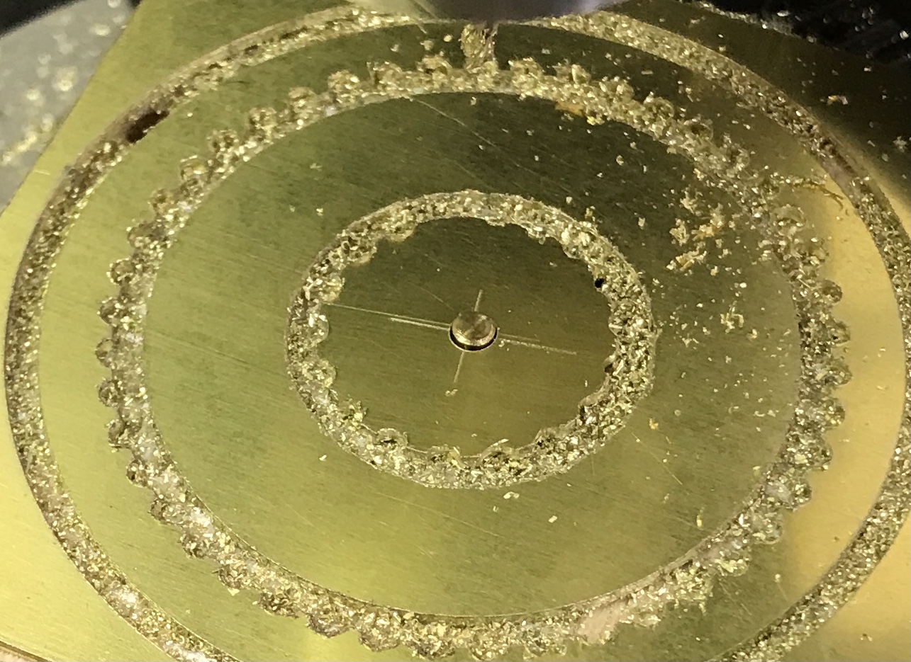
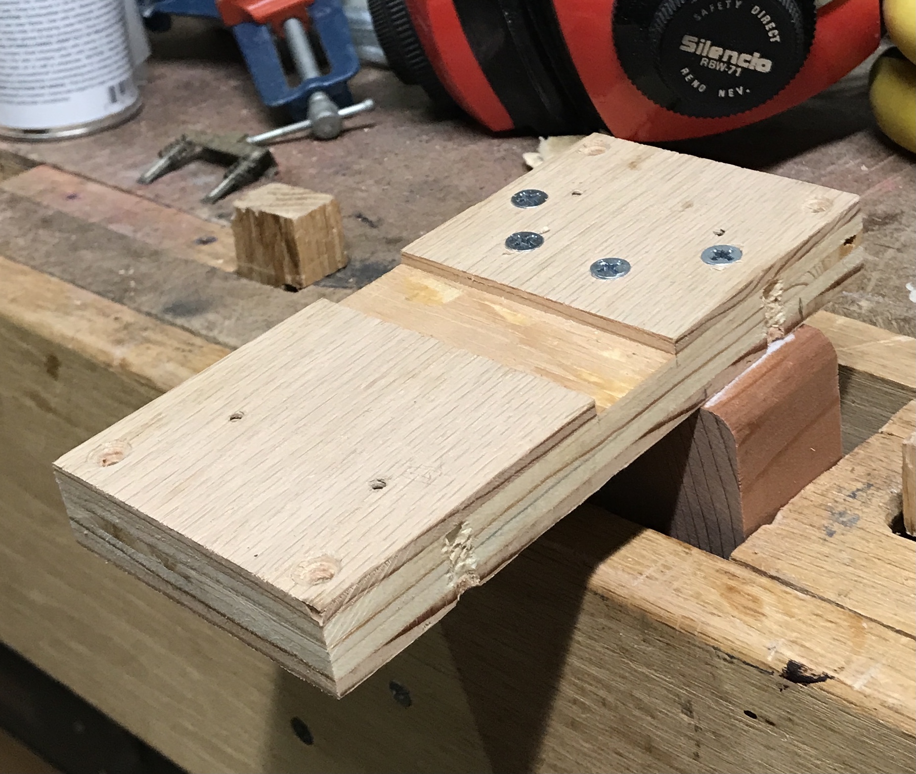
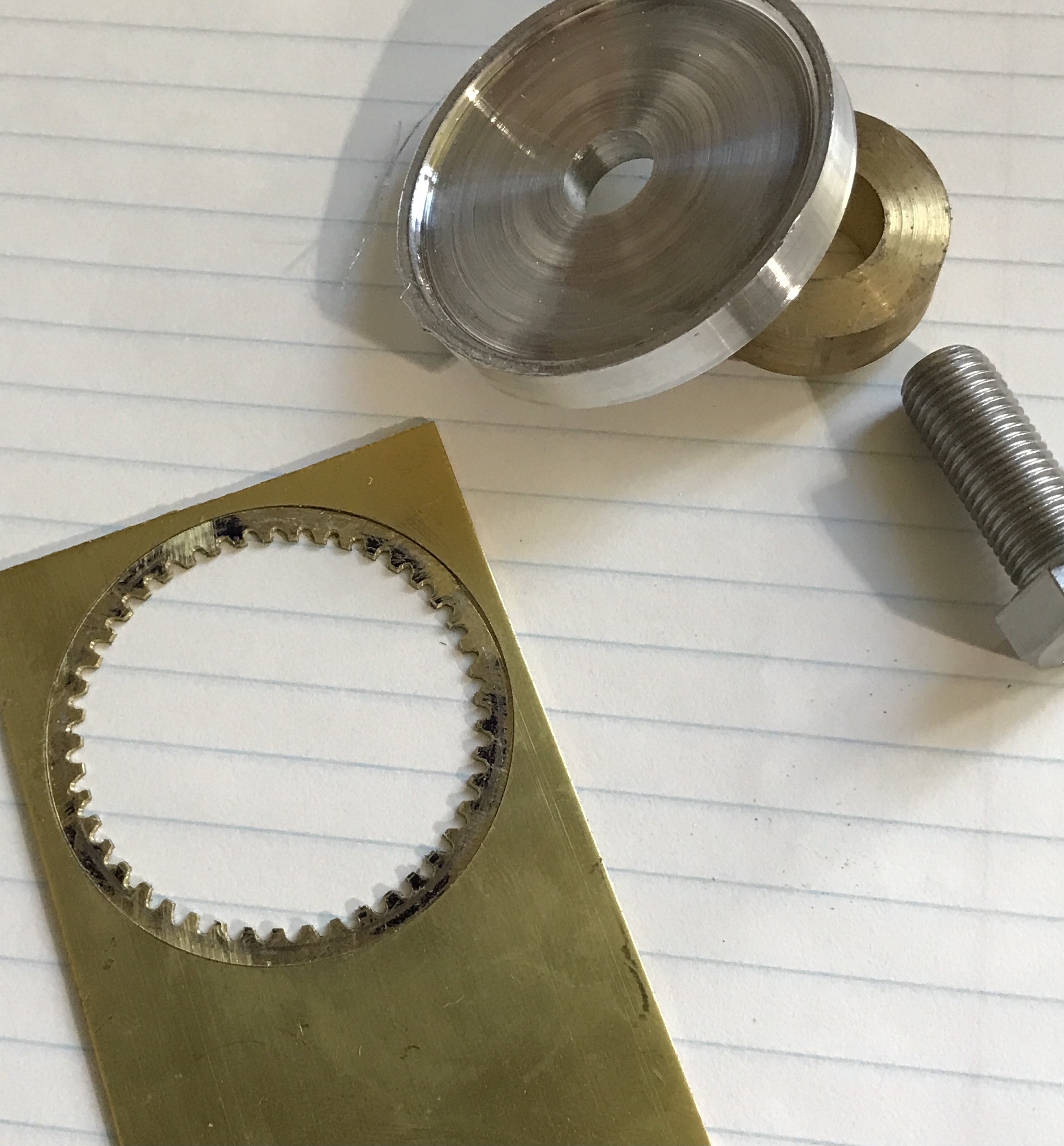
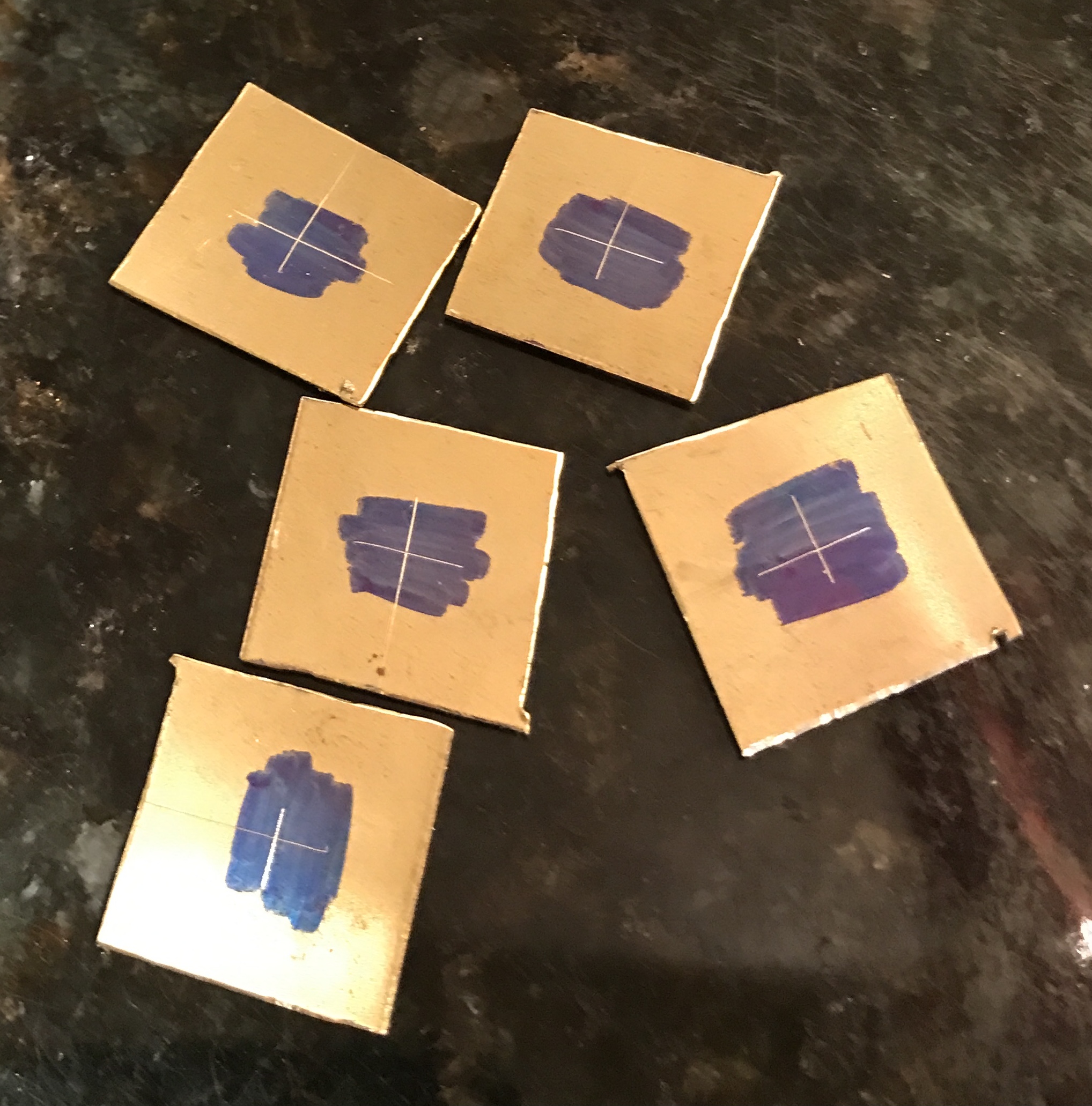
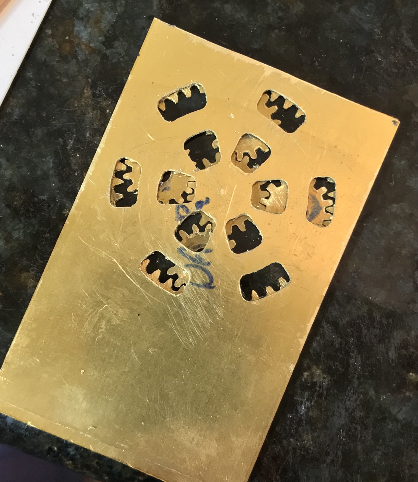
The parts were removed from the block and the excess carpet tape glue was cleaned off with mineral spirits. The two gears were "painted" with a Sharpie prior to marking. The large internal gear was held on the outside of the jaws in a three-jaw chuck. A sharp cutting tool was aligned with the tip of a tooth. The cross slide was moved 0.072". A circle was scratched on the brass marking the depth of cut. Similarly, the central gear was held in the chuck aligned with a 5/16" drill. Again the cutting tool tip was aligned with the tooth top and the carriage moved 0.072" prior to scratching the gear. The pictures below tell the story.
The gears were cut with a hack saw blade. This produced a square cut at the center of the end mill cut. The cut was made down to the line. This was done on both the large gear and the central gear.
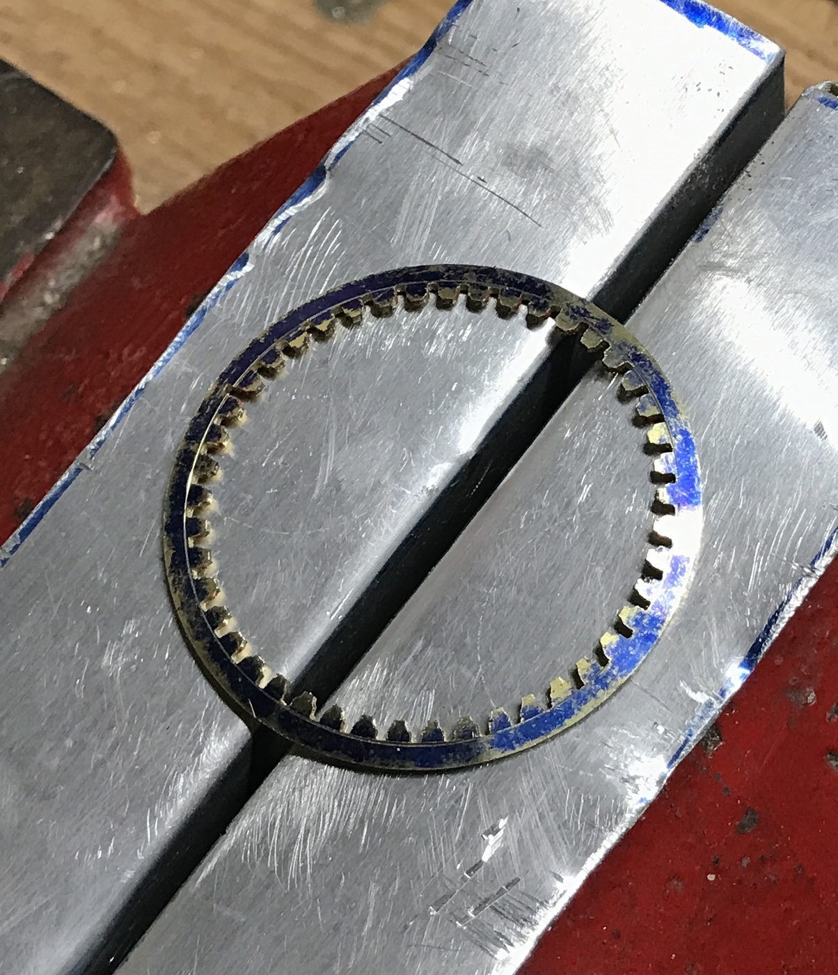
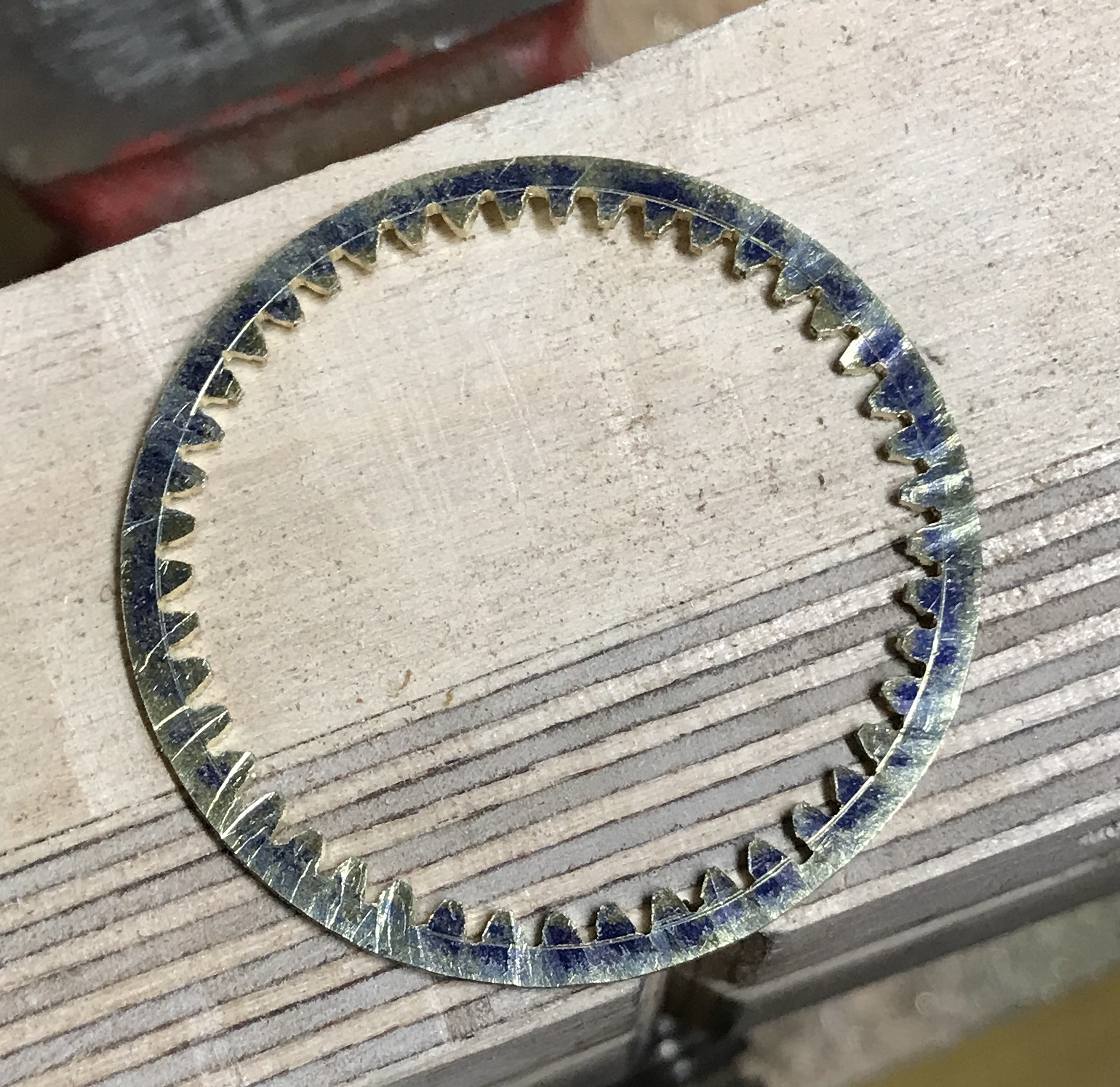
Filing was tackled next with a needle file having a skinny trapezoidal cross section. The large internal gear required significant thinning of the teeth and shaping so they were not so triangular. The central gear required less filing, but some of the teeth seemed to be at an angle. This was most likely due to a hacksaw cut that was not square. For the most part the central gear can rotate in the large gear. The thinning of the teeth in the large gear between the two photos below.
The card proper needs a number of things done to complete it. The openings in the top sheet need to be cut out using the rotary table. The three sheets need to be clamped/glued to one another to have the edges cleaned up, the corners drilled, and the round openings cut into two sides.
The openings in the top sheet are essentially arcs from two circles. The inner series of six arcs are 1/4" wide, while the outer series are 3/16" wide. The outer sides of the inner series of arcs are 15/16" in diameter. The inner diameter of the outer series of arcs is 1 1/4". O.D. is 1 5/8". They are not designed to be cut in one pass with an end mill. Only the outer corners of the outer series are rounded. The rounded corners are about 1/16" radius. The ends are not on radii of the circle, but are offset. The offset is 3/64" for the inner series and 3/32" for the outer series.
I am having second thoughts about this project. The hand-formed gear teeth are pretty poorly formed. Every step in this project seems to be more of an approximation than an exact cut. The measurements are never exact. The gear teeth are not very good. Even the top sheet will have to approximate the plan. Unfortunately, the approximations add up to more errors. I am rethinking how I might redesign this planetary card to fit better with the equipment I have at hand. I also need a better way to make the teeth on these gears. I plan to review an old video I have on gear making. It covers making a hob, which would be free as opposed to buying expensive gear cutters. This might be a great opportunity to relearn Fusion 360 and make a slotting attachment for the mill.
The slotting attachment is completed, so it time to return to the business card. After reading about internal gears it became clear to me that the parameters for the internal gear are calculated the same as for a spur gear, except the internal gear is inside out. Looking carefully at the gear profile for the internal gear in the plan above makes this evident. The gaps between the teeth are shaped like spur gear teeth and the teeth are shaped like the gaps in spur gears. The following two tables summarize the best estimate of the three gears as measured from the plan and what a true 30 DP set would be like. (This assumes a 20° PA.)
| Internal Gear | Planetary Gear | Central Gear | |
|---|---|---|---|
| Outer Diameter (measured) | 1.580 | 0.563 | 0.656 |
| # Teeth | 45 | 14 | 17 |
| Diametral Pitch = (#T + 2)/OD | 29.75 | 28.4 | 28.9 |
| Whole Depth = 2.25/DP | 0.076 | 0.079 | 0.078 |
| Pitch Diameter = #T/DP | 1.513 | 0.493 | 0.588 |
Theoretically, the pitch diameter of the internal gear should equal the PD of the central gear plus twice the PD of the planetary gear or 0.588 + 2(0.493) = 1.574 not 1.513!
| Internal Gear | Planetary Gear | Central Gear | |
|---|---|---|---|
| Outer Diameter = (#T + 2)/DP | 1.567 | 0.533 | 0.633 |
| # Teeth | 45 | 14 | 17 |
| Diametral Pitch | 30 | 30 | 30 |
| Pitch Diameter | 1.500 | 0.467 | 0.567 |
| Dedendum = 1.25/DP | 0.042 | 0.042 | 0.042 |
| Addendum = 1.0/DP | 0.034 | 0.034 | 0.034 |
Here the PD's add up. 0.567 + 2(0.467) = 1.501 Though it probably makes sense to cut the planetary gears a bit smaller to build in some play.
The middle plate has the squarest corner. This corner will be used to align the other two cards prior to corner drilling and milling to size. The side indentations will also be cut. These cuts will free up the middle plate, so the corners must be drilled first. Consequently, the size of the opening is now determined. This opening is 1.844" in diameter. The internal gear will be this diameter minus 1/64" or 1.828". The internal gear will be cut on the rotary table. Leaving it in place sets it up to use the slotting attachment for cutting the internal gear teeth.
The plan for cutting the internal gear is as follows: tape a slightly oversized square of brass to a block of wood that is center drilled to fit the rotary table stub. Mill the square of brass to a 1.828" diameter circle. Mill a circle out of this leaving a 1.567" diameter hole. Remove the cutout and then mill out the wood leaving a depression in the center of the brass ring. Mill partial openings for the 45 gaps between the teeth. Use the slotting attachment to finish cutting these openings.
The slotting attachment should be experimented with prior to doing any of the work listed in the above paragraph. Tools should be made for the two needed profiles and used to make a gear or two before experimenting on the real thing.
Such an attempt was made this morning. The 1/4" tool steel that was pounded through the slotting attachment ram was painted with Dykem and a gear cutting shape was scratched into the top of the tool. The tool was ground with the new grinding wheels. Care was made to have at least 15° of clearance as the hole in the ram for the bit sits at 10°. The bit was put into the ram and the slotting attachment was installed on the mill. A scrap of 1/32" brass was attached to a block of wood with carpet tape.
The cutting tool was aligned with the edge of the brass and it was slowly advanced in 0.001-0.002" increments.The first thing noticed is that there is play in the ram! The bottom bearing is not a tight fit, unlike the top bearing. This made advancement somewhat tricky. After proceeding to a depth of about 0.090" cutting was stopped for an assessment. The brass has a wider and rounder opening than the tool bit should have provided. In addition the brass was clearly bent around the cut.
The ram runout needs to be fixed. This should improve the shape of the resulting cut. The brass also needs a firmer support than provided by the block of wood. Maybe an aluminum backing will prevent the bending.
With the bearing on the ram repaired another attempt was made to cut with the slotter. A scrap of brass was clamped to a piece of aluminum with two machinist's clamps. One of the clamps was held in the vise. Cutting with the gear tooth-shaped tool was attempted. There were two problems that arose. The vise did not hold the clamp tightly enough for the pushing when the brass was sitting so far from the vise. The second problem was the table was not moving correctly when dialing another 0.002"!
The problems with the table were fixed by removing the handle, loosening the retaining ring, pulling the screw hard to the right, tightening the ring, and reattaching the handle. Some crap was also cleaned out of the handle. Another means of holding clamps in the vise was devised. This system worked better except the brass was not far enough above the vise to allow cutting fully through the brass. A larger piece of aluminum needs to be found to give this arrangement a better test.
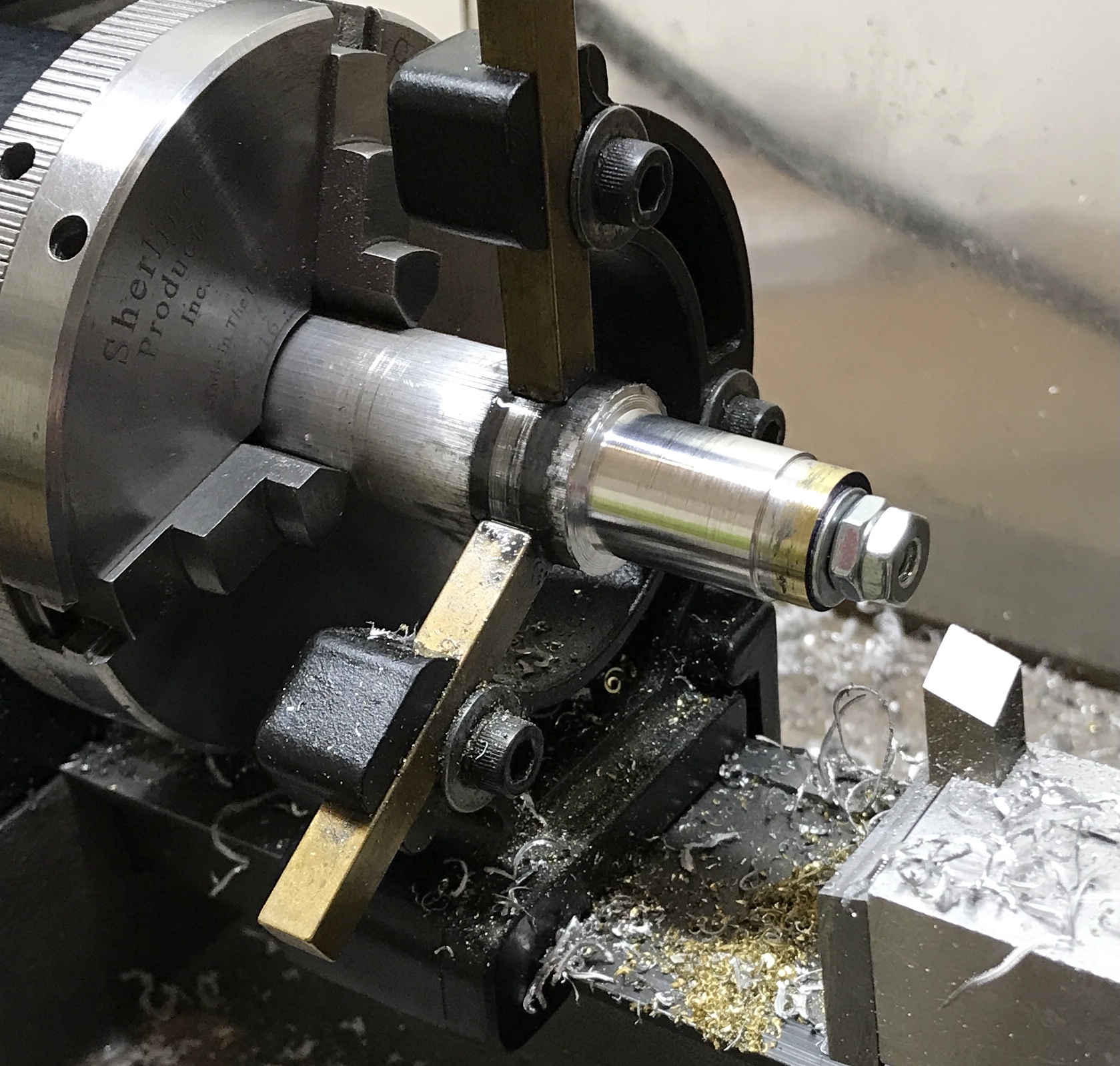
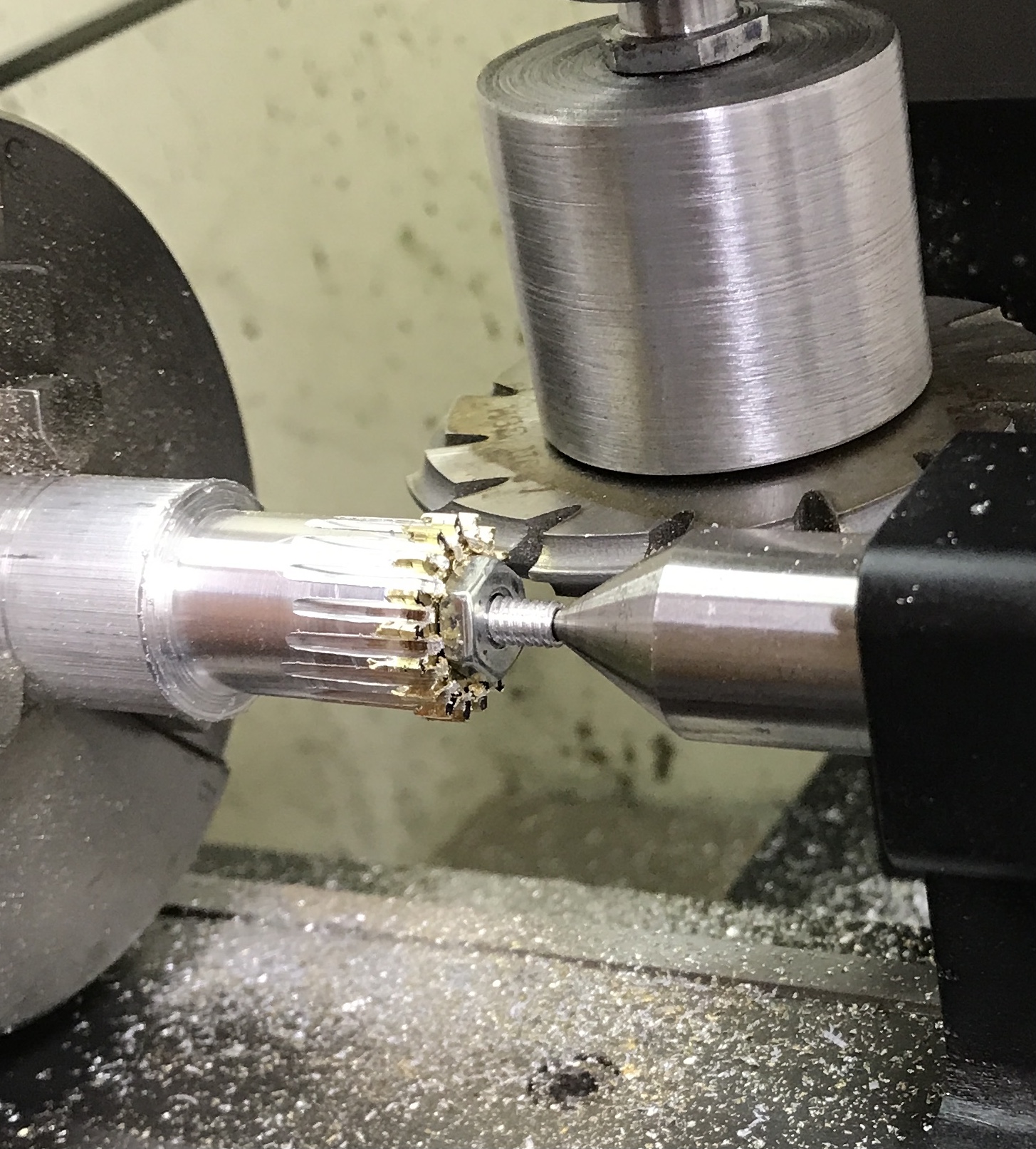
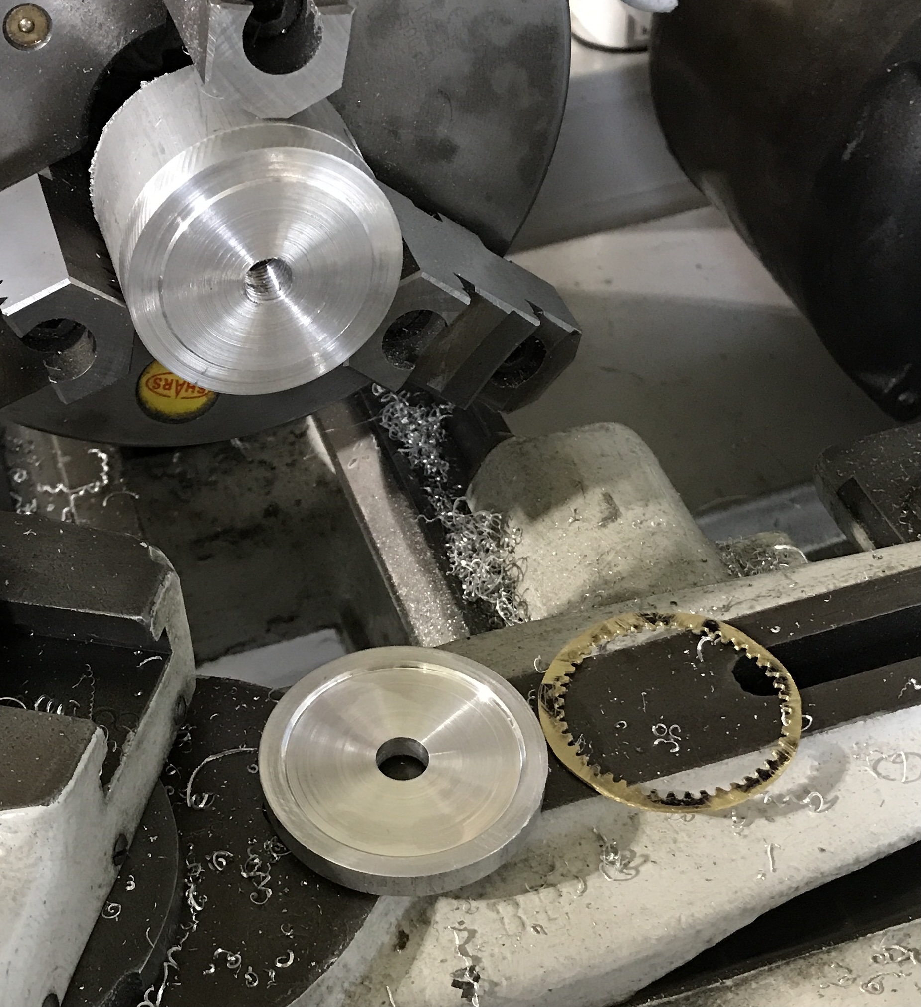
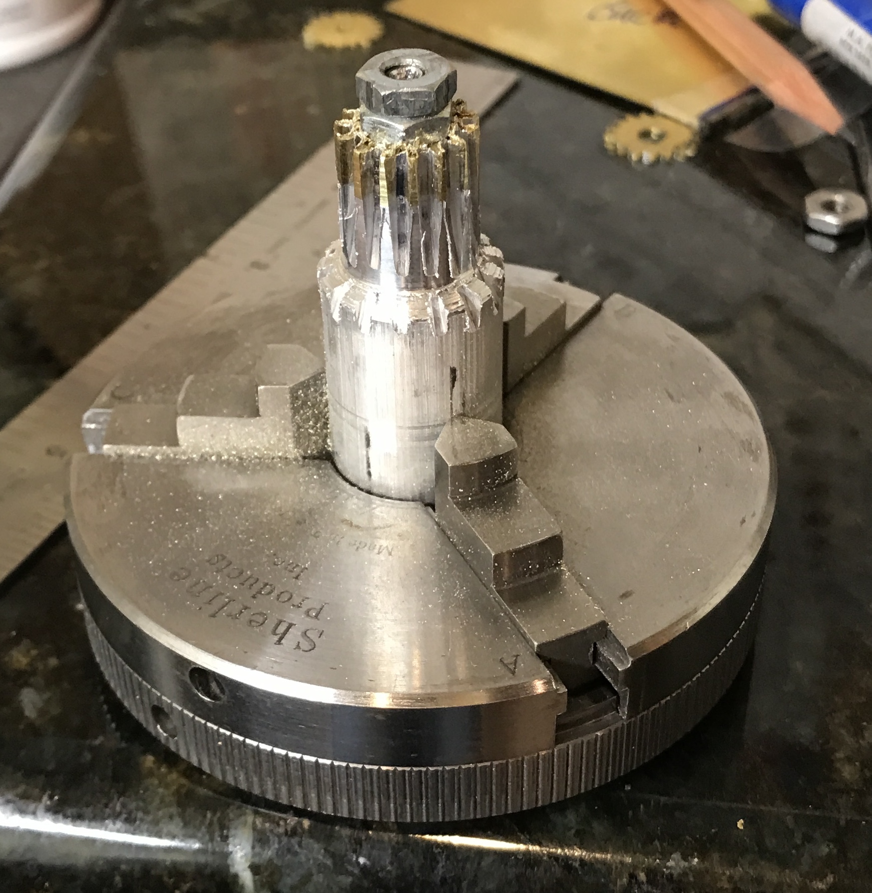
Before continuing with the outer gear the planetary gears will be tackled. A #7 gear cutter will be used. After a short break the planetary gears were tackled this morning. A mandrel was made to hold the four 5/8" brass squares. A 2 3/4" length of 3/4" aluminum was cut and held in the lathe chuck. Both ends were faced. A steady rest was used. One end was reduced to 0.164" for 1/2". This end was threaded 8-32 with the tailstock die holder for 3/8". The pre-drilled brass squares were placed on the mandrel followed by a washer and two nuts. The squares were reduced to circles and then to 0.531". A further 3/4" of the mandrel was reduced to 0.55". The mandrel holding the gear blanks is shown below.
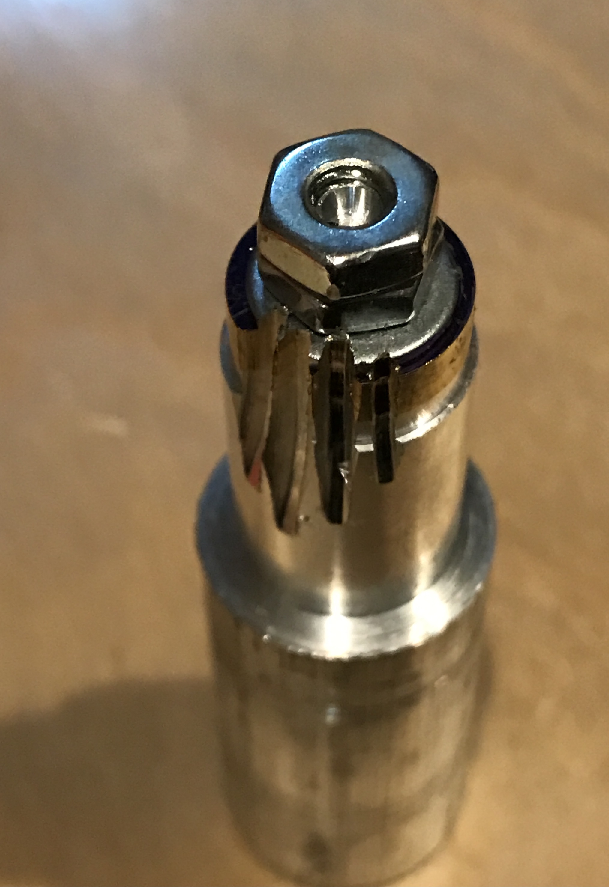
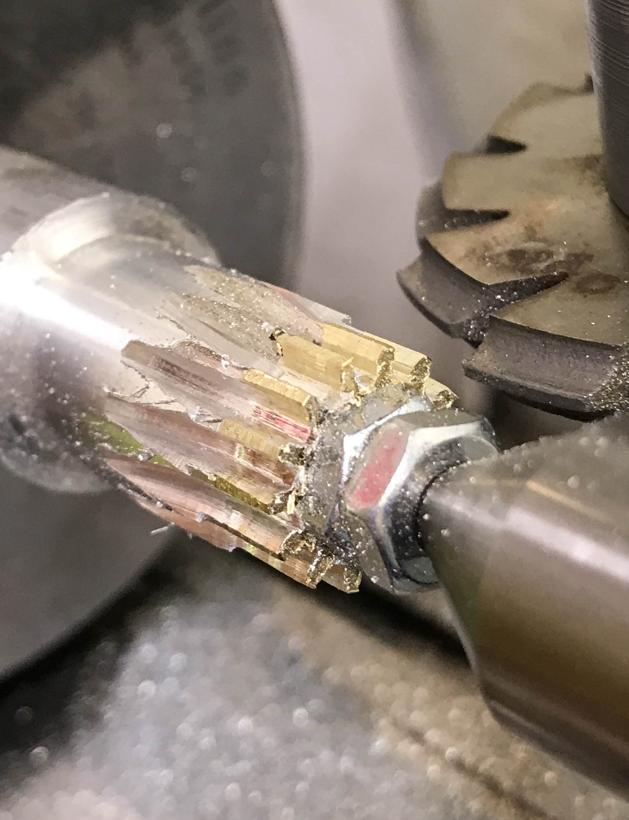
Months later I am getting back to this project (March 31 to July 6). I didn't write down the problem that led to temporary abandonment. Looking at the attempt to cut the planetary gears gave a pretty good idea of the problem. The teeth look awful. A steel washer was part of the problem. The rotations do not look even. The tooth shape is all wrong. I am guessing that chatter was a major problem. Movement would certainly account for the poor tooth shape.
The first thing to be done is making new planetary gear blanks. Five squares about 5/8" on a side were cut from the 1/32" brass sheet. They were marked for holes and drilled with a #19 drill to fit the mandrel. The squares were put on the mandrel without a washer. Two nuts were used to hold them tight. They were turned down to 0.530". The mandrel still held in the three jaw chuck was moved to the Sherline indexing table. The tailstock center was pushed tightly against the free end of the mandrel.
After measuring the length of the extended rack the Calculator for the Sherline Dividing Head was used to produce a table of rack offsets. The first gap was cut in increments of 0.005". It is slow going as the cutter wants to stall. The cut was made to a depth of 0.072". The process is extremely loud, so it will be finished this afternoon when Rhea is teaching dancing in the garage.
Very slow going. It was shortened a bit by increasing the depth of cut to 0.010" for the first five cuts. Six gaps have been cut so far. The next one will begin tomorrow morning at offset 3.905". Four more were cut and then the spindle became so tight it could not be turned?!? I had to turn the spindle backwards until it would be loose enough to get through the remaining cuts. This lost the alignment. The cutter was aligned as well as possible in the last gap cut. All of the gaps are separated by 0.3366. The last five cuts will be based on adding this to the measured position of the rack.
The cutter was centered as well as possible in the last slot cut. The rack was moved -0.3366 and the next cut was made in ten passes as above. The rack was moved the same amount and the the next cut made. Three more cuts were made to finish the gears. The photo attempts to show how nice the teeth look. The end was cleaned up with a file.
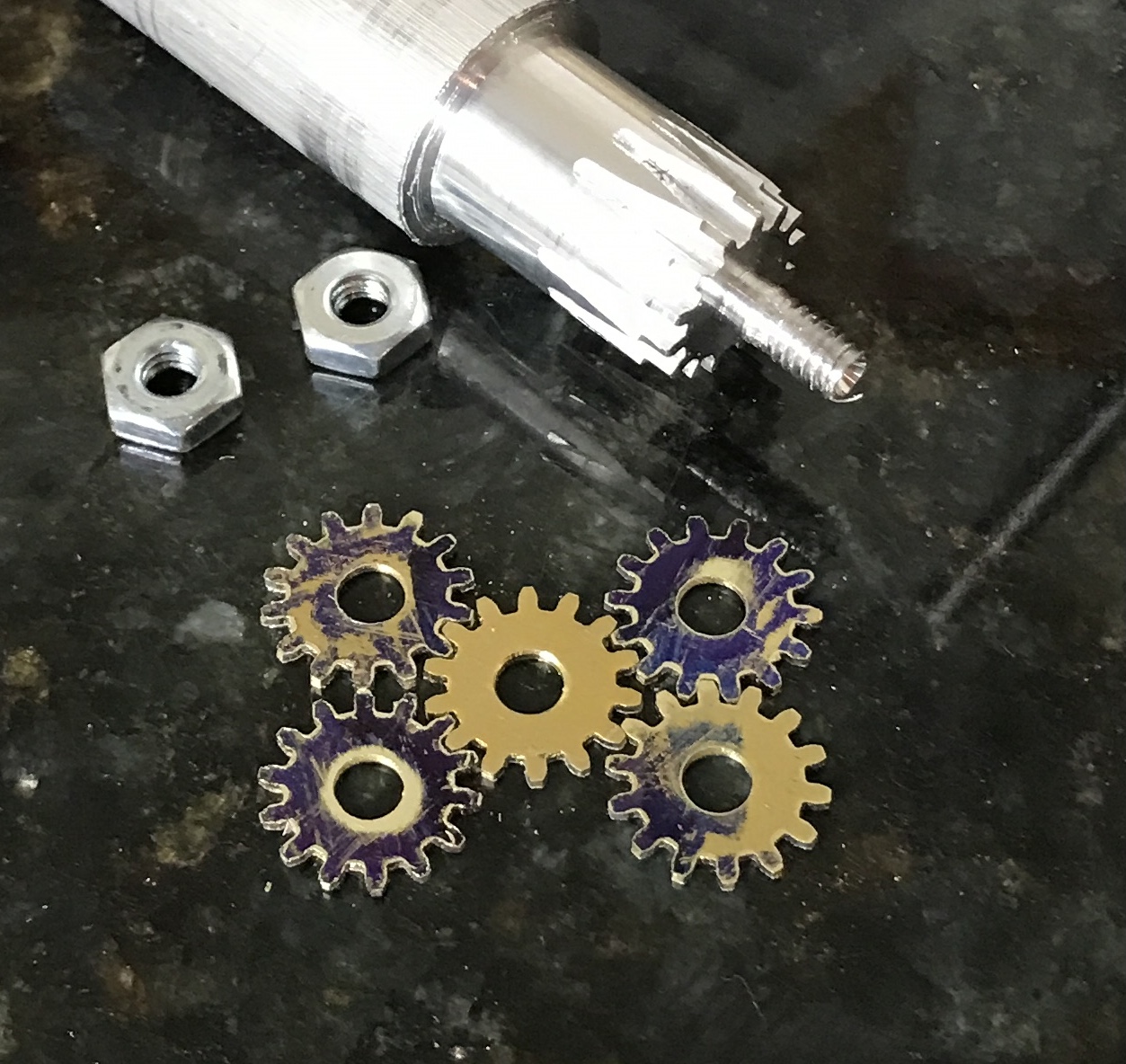
After the beating the setup took from the intense chatter, it was no surprise that the chuck was very difficult to open. The nuts were removed from the mandrel. The five gears were stuck together and were removed as a unit. The last gear (closest to the mandrel) had burrs that were embedded in the aluminum behind it. This gear came loose the easiest. The other gears required some sharp raps with a makeshift hammer, the back of the mandrel. All gears were filed on both sides. The photo shows the resulting five gears.
The problem with the gear cutting was discovered. The cutter holder is not all concentric. The body of the holder was aligned to within 0.001" in the chuck. The dial indicator was moved to the shaft that sits in the mill's collet. The shaft was out of alignment 0.003" close to the body and 0.003" farther from the body. The shaft needs to be remade in situ. It is not clear how to reconcile this with the description of runout when this gear holder was made. Attempted to make another this morning using a collet in the South Bend. Unfortunately, the last step, threading, the die went on crooked! Should have single pointed the threads. A new gear cutter holder was made with many detours.
The central gear was made this morning. Two square blanks slightly larger than 5/8" were cut from 1/32" brass stock with a hacksaw. A hole was drilled in the center of each with a 0.166" drill. The mandrel had to be remade by cutting off the threaded portion, reducing 1/2" to 0.164" and threading it 8-32. The blanks were placed on the new threaded shaft and a nut was tightened to hold them in place. The blanks were reduced to 0.633" circles.
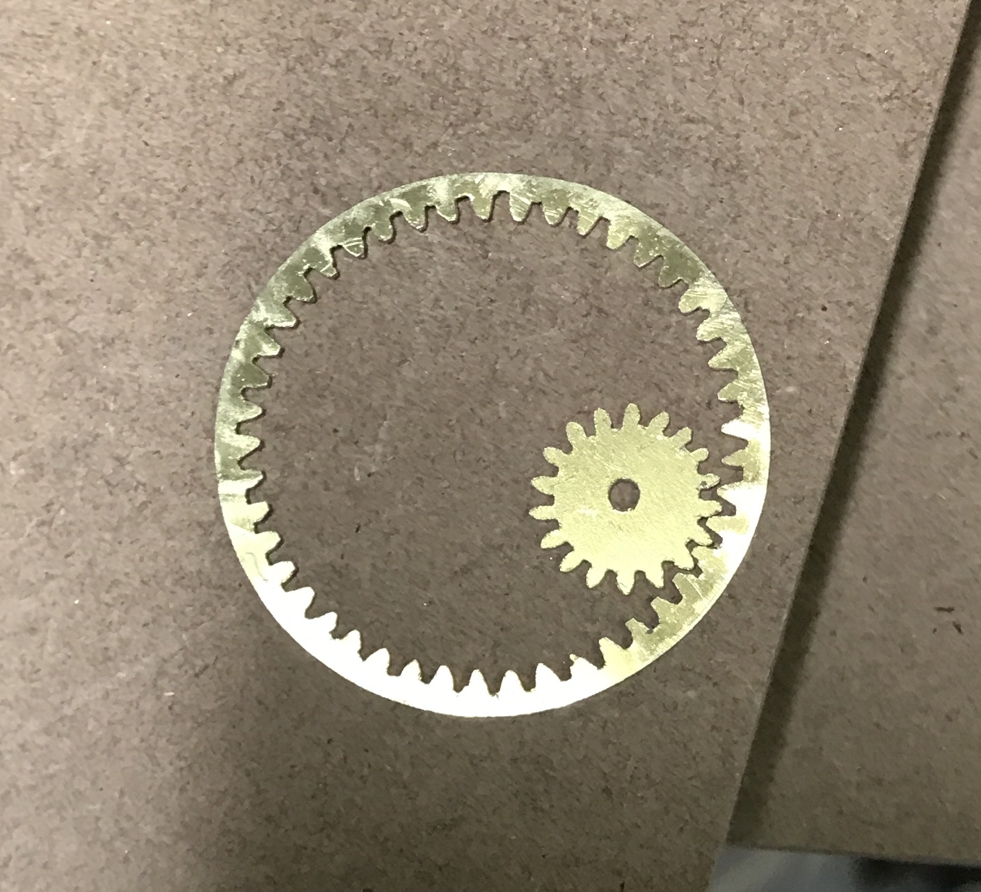
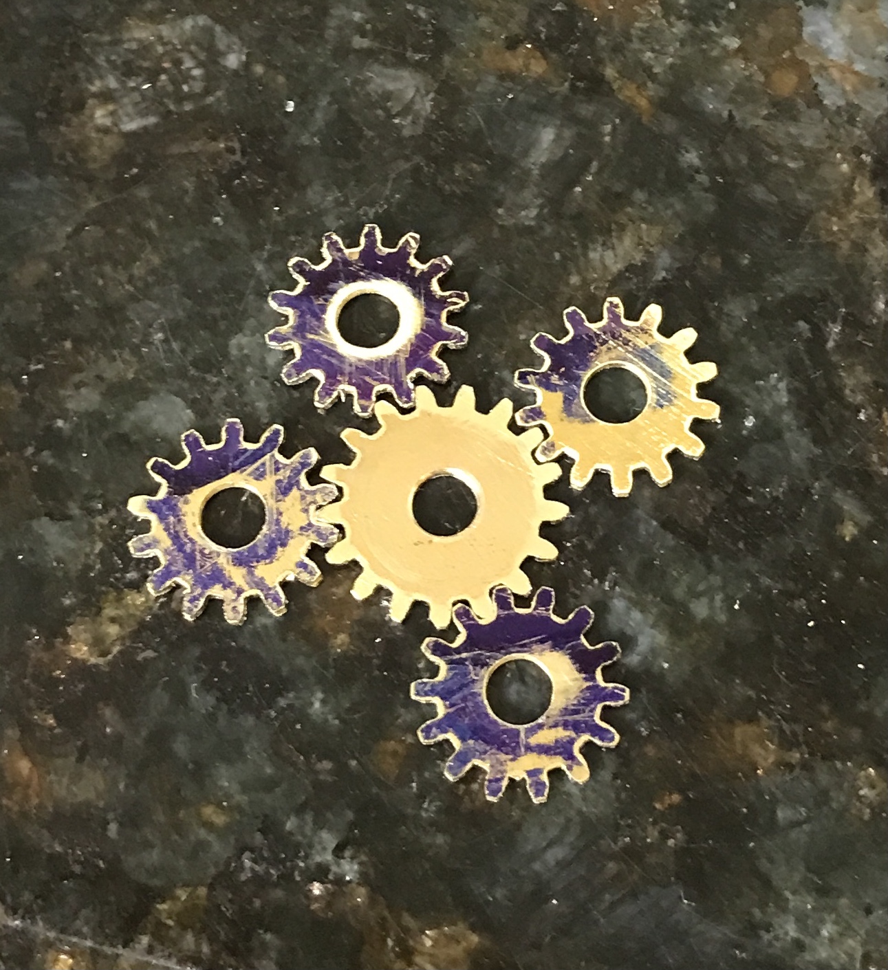
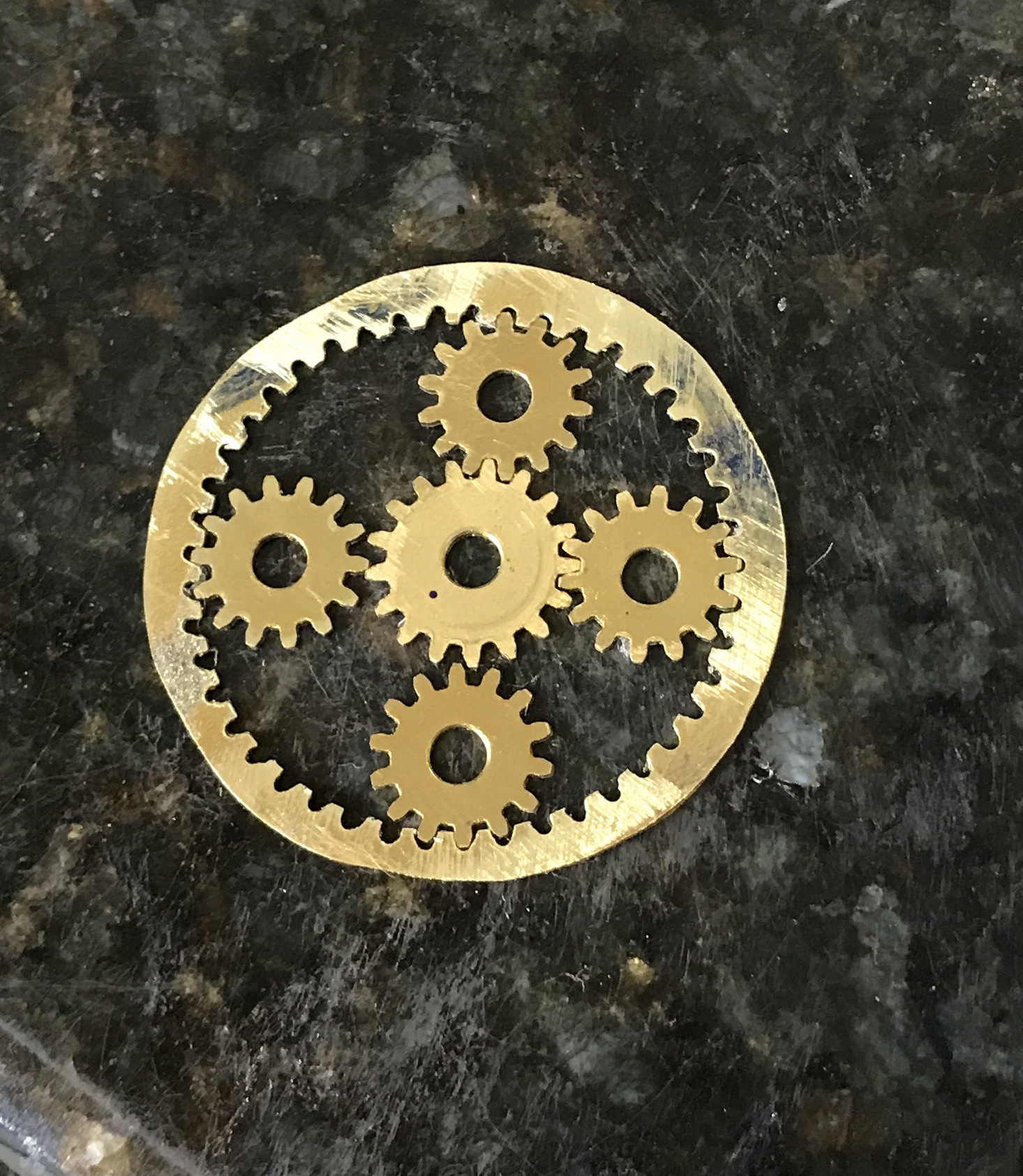
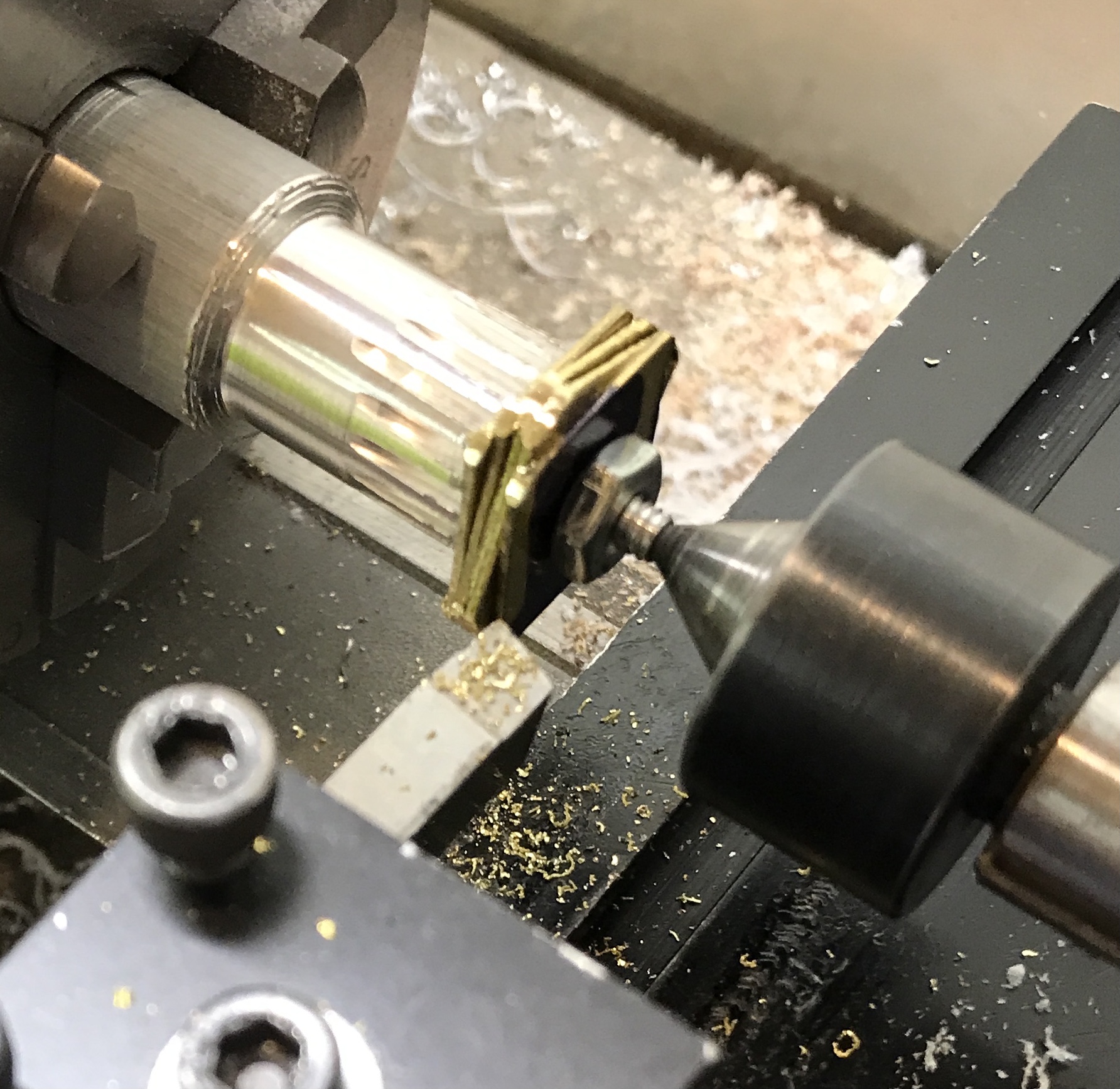
The three jaw chuck holding the mandrel was moved from the lathe to the indexing attachment. This was attached to the milling table. The #7 cutter was placed on the cutter holder made above. (A #6 cutter should have been used for a 17 tooth gear, but I don't have one.) The gear cutter was lowered to the top of the blanks and then lowered 0.1075" + 0.3165". The teeth were cut according to the offsets produced by the Gear Cutting Calculator. The teeth were cut to a 0.072" depth in ten decreasing passes. The gears were removed and cleaned up with a file. Separating them was a challenge, but one eventually overcome. The first picture below shows the completed gears still in the mill. The second shows one of the two gears surrounded by four planetary gears.
The new gear cutter holder worked well. The noise was significantly less painful than when cutting the planetary gears. It was also obvious that more teeth were engaged in cutting. A successful, but not perfect, gear cutter holder.
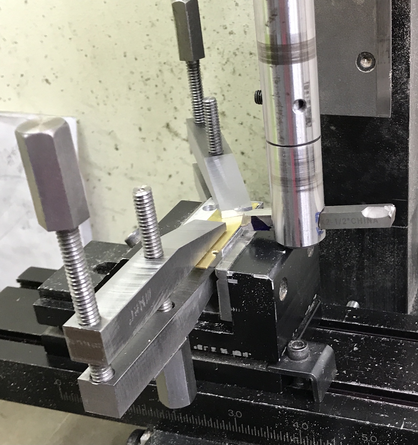
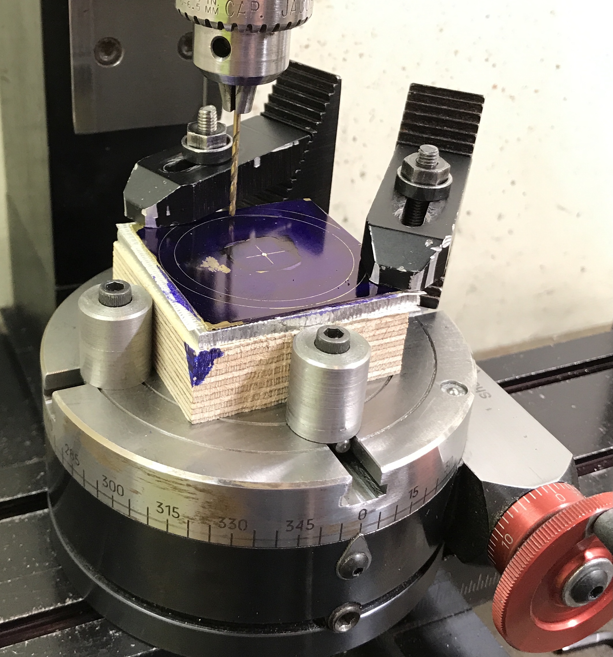
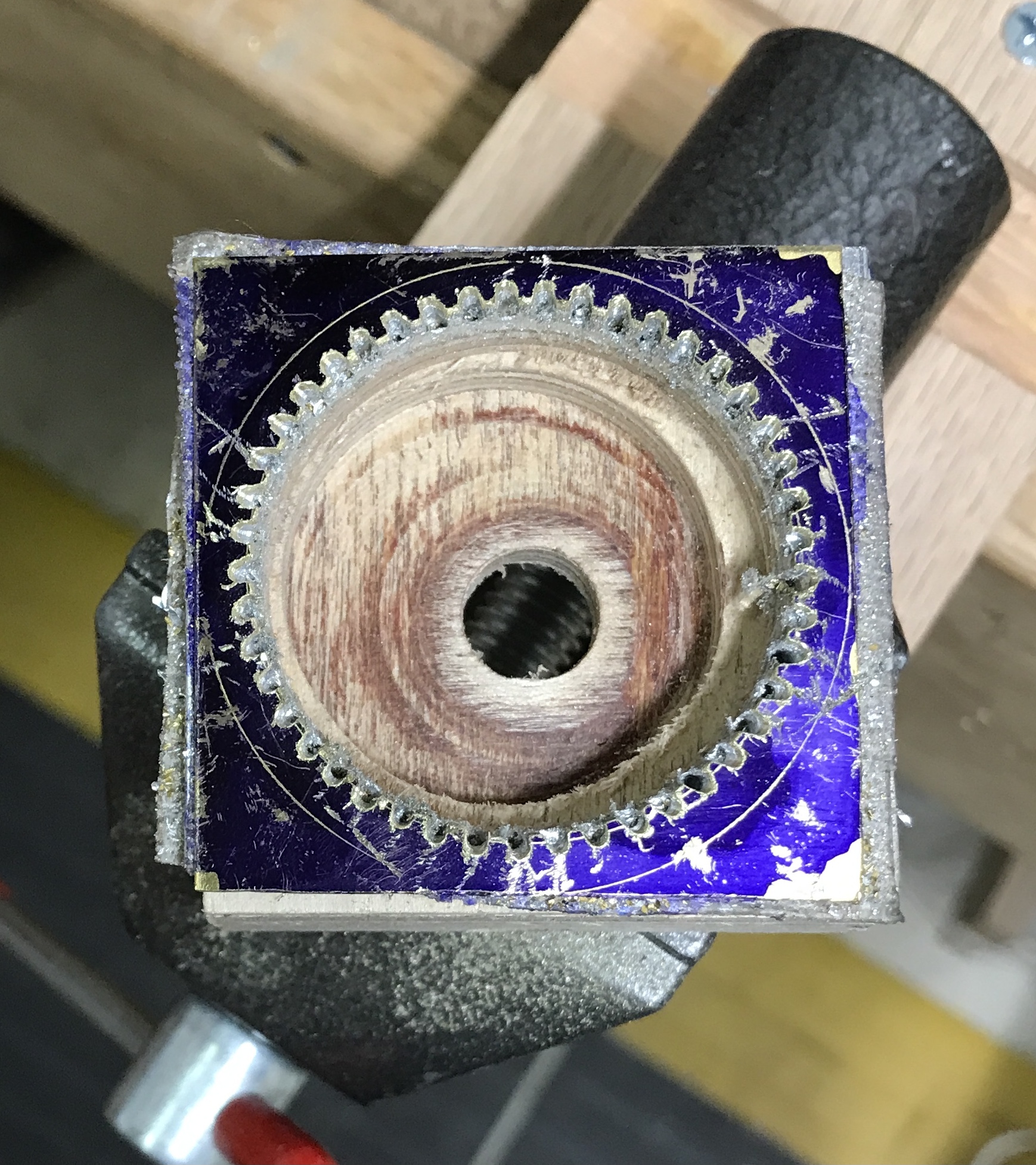
The internal gear was next on the agenda. A square of brass, 1.875" on a side, was taped to a similarly sized square of 1/8" aluminum, which was taped to a same sized square of plywood. The center of the brass was located and punched. Two circles were marked out at 1.567" and 1.828" diameters. The block of material was placed on a centered rotary table in the mill. The block was adjusted to center using the slip-on-spud. It was clamped in place with two strap clamps. Two round blocks were used as stops around one marked corner. The photo shows the setup.
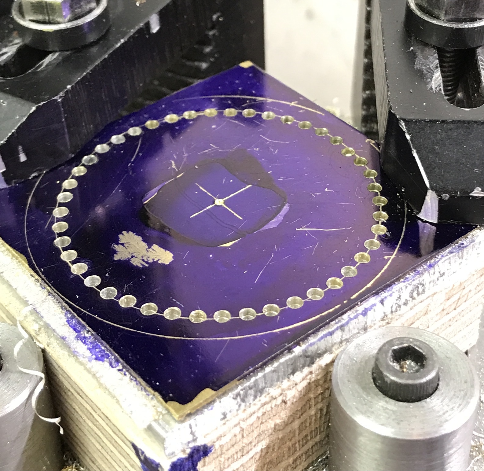
The table was offset on the y-axis 0.7835". A 1/16" drill was used to drill holes every 8° around the circle. The holes were drilled through the brass and aluminum and into the wood underlayment. The forty-five holes were drilled in fifty-two minutes. The following photo shows the completed forty-five holes. They are not perfectly aligned with the marked circle.
The initial plan changed. The table was moved 1/16": spindle toward the center. A 1/8" drill drilled a hole through to the wood. The drill was switched for a 1/8" end mill. The end mill was advanced in 0.02-0.03" increments and a circle cut through the brass, aluminum and into the wood. The brass circle was removed when it was cut free. At this point the aluminum was removed.
The hole needs to be at least 3/8" deep for the slotting tool to get through the brass and deeper to get through the aluminum. An attempt was made to use a chisel to remove wood in the center. This was not very effective. The block was moved to the four-jaw chuck on the lathe. It was drilled up to 3/8" and then bored out to the groove cut with the end mill. The photo below shows the completed boring operation.
The block was returned to the rotary table using the two stops for centering with the marked corner between them. Almost two months later I am returning to this project. The mill table has had the rotary set up on it this entire time, so I have not had access to the mill. The shaper was used in its stead for the QCTP base plate. Fighting off the effects of the two vaccines received yesterday, flu and covid. Not sure I will get much done.
After some monkeying around trying to set the part up correctly I decided to at least try out cutting one gap. The tool bit was sharpened and the slotting attachment was installed. The cutter was aligned with one drilled hole and the an attempted cut was made. There was just too much play in the slotting attachment. I would get a good cut and then after moving the table 0.001" I could not get through the brass. This approach was abandoned. I can think of no better path forward than returning to the file.
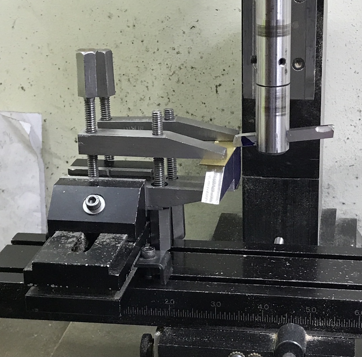
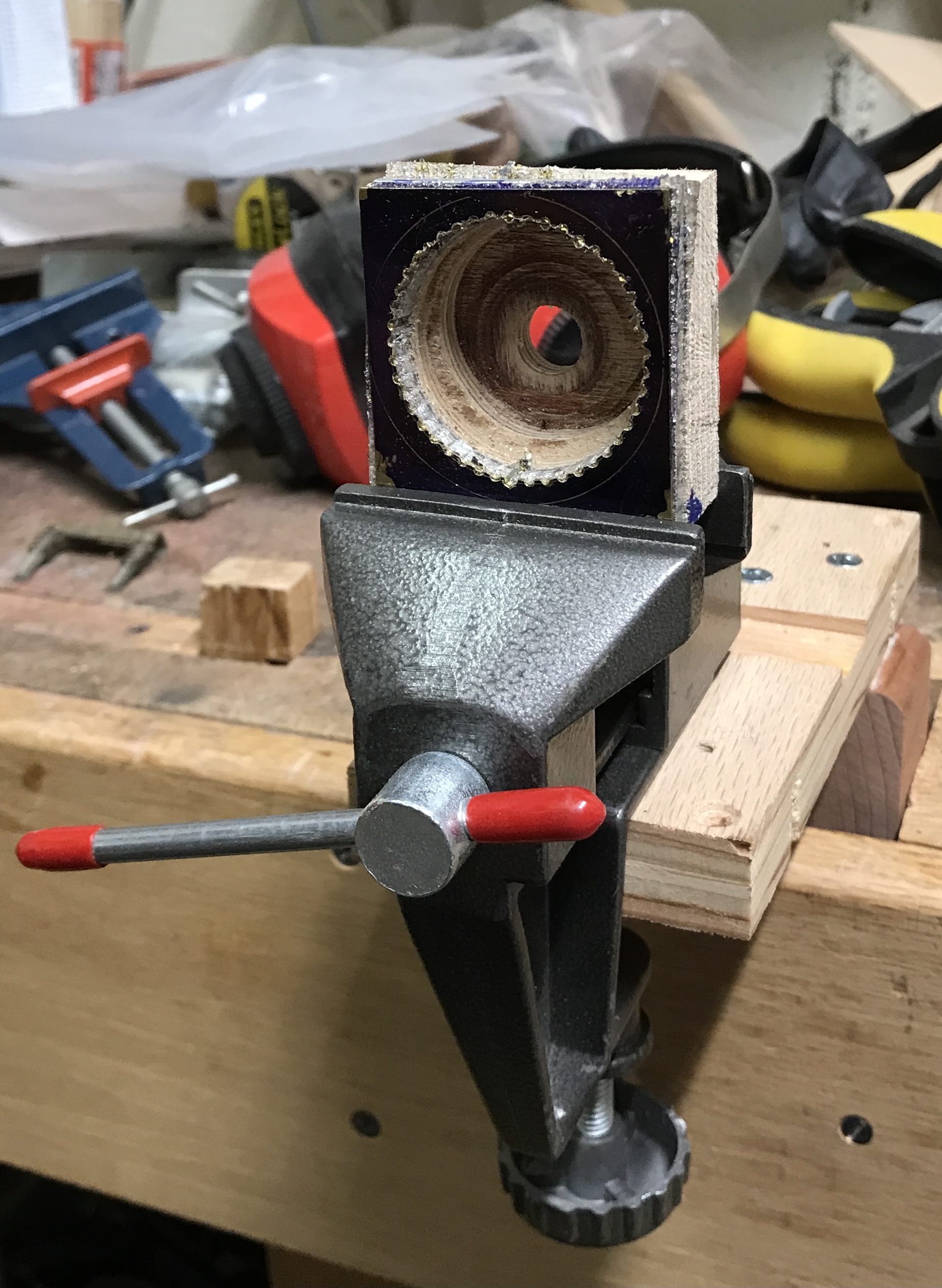
I am going to try out some very small burrs for the Dremel to cut the gaps between teeth on the inner gear. I need a way to clamp the block securely. I found an old vise that clamps to a table or board. An appropriate "board" was made from scrap, which was clamped in the end vise on the workbench as seen in the photo below.
The Dremel worked pretty well, giving reasonable gear teeth shaped gaps. The next step was cutting out the circle. The rotary table was recentered and the block centered on the table using the central 3/8" hole. This was a mistake. The larger hole was not concentric with this hole. Cutting was begun and I quickly realized the error. The 1/8" end mill was moved further out and a rough approximation of a circle was cut. The gear was freed from the block. It was filed roughly to shape by hand.
To fit in the central hole of the middle card the internal gear needs to be cut round. The morning was spent making a mandrel for holding this gear, so it can be cut to size. A 2" round scrap of aluminum was located. One end was cut off and faced to serve as the cap. This plate was held in the lathe and aligned with parallels. It was faced and drilled through with a 24/64" drill. A 0.06" deep well was cut in the face that is wider than the ID of the gear.
The rest of the scrap was placed in the lathe and faced. It was turned down to fit the internal gear to a depth of 0.025". This part was then drilled with an 'O' drill and tapped 3/8-24. The gear fits tightly and the cap sits on top. Unfortunately, I have not been able to find a 3/8-24 screw. The mandrel will remain in the lathe until it is used. I don't want to mess up the concentricity.
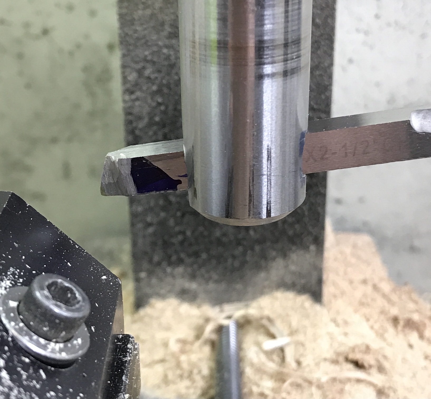
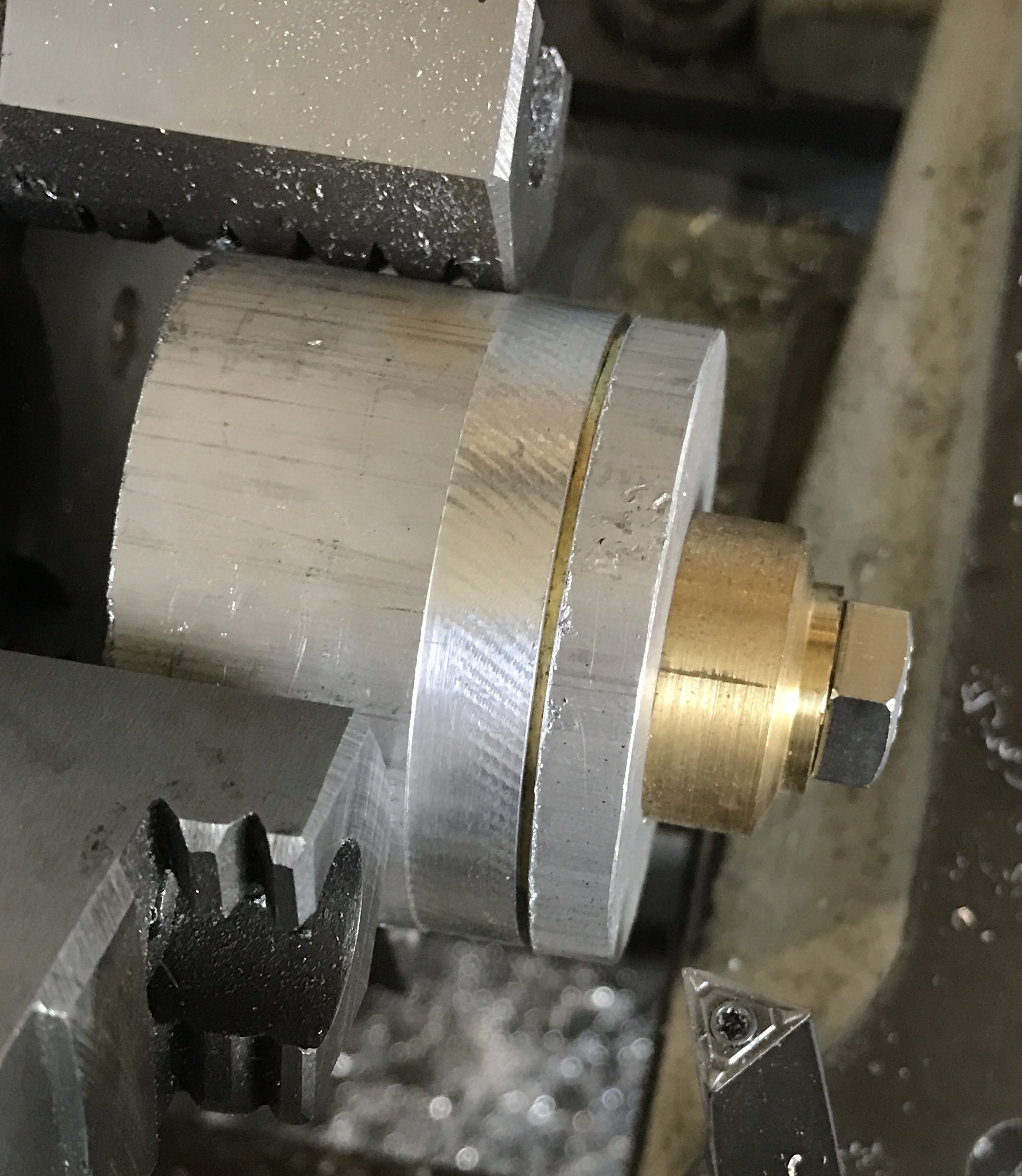
Finally made it to Menards to pick up a stainless steel screw. It was installed and found to be too long. A scrap of brass was used as a washer. The internal gear ring was pressed on and the cap screwed tight. The cap and mandrel body were slightly larger than the gear. The mandrel was cut down to size. The gear was slowly reduced in 0.005" increments. The cutting was stopped when there was about a 1/2" of flat left on the gear. The gear was removed and placed into the opening in the central card layer. A perfect fit. The first photo shows the setup, the second the partially finished cut, and the third the fit.
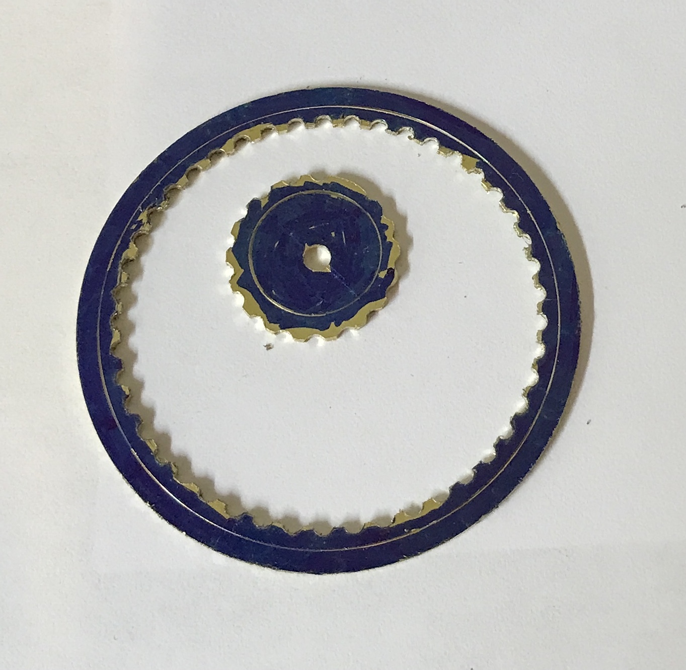
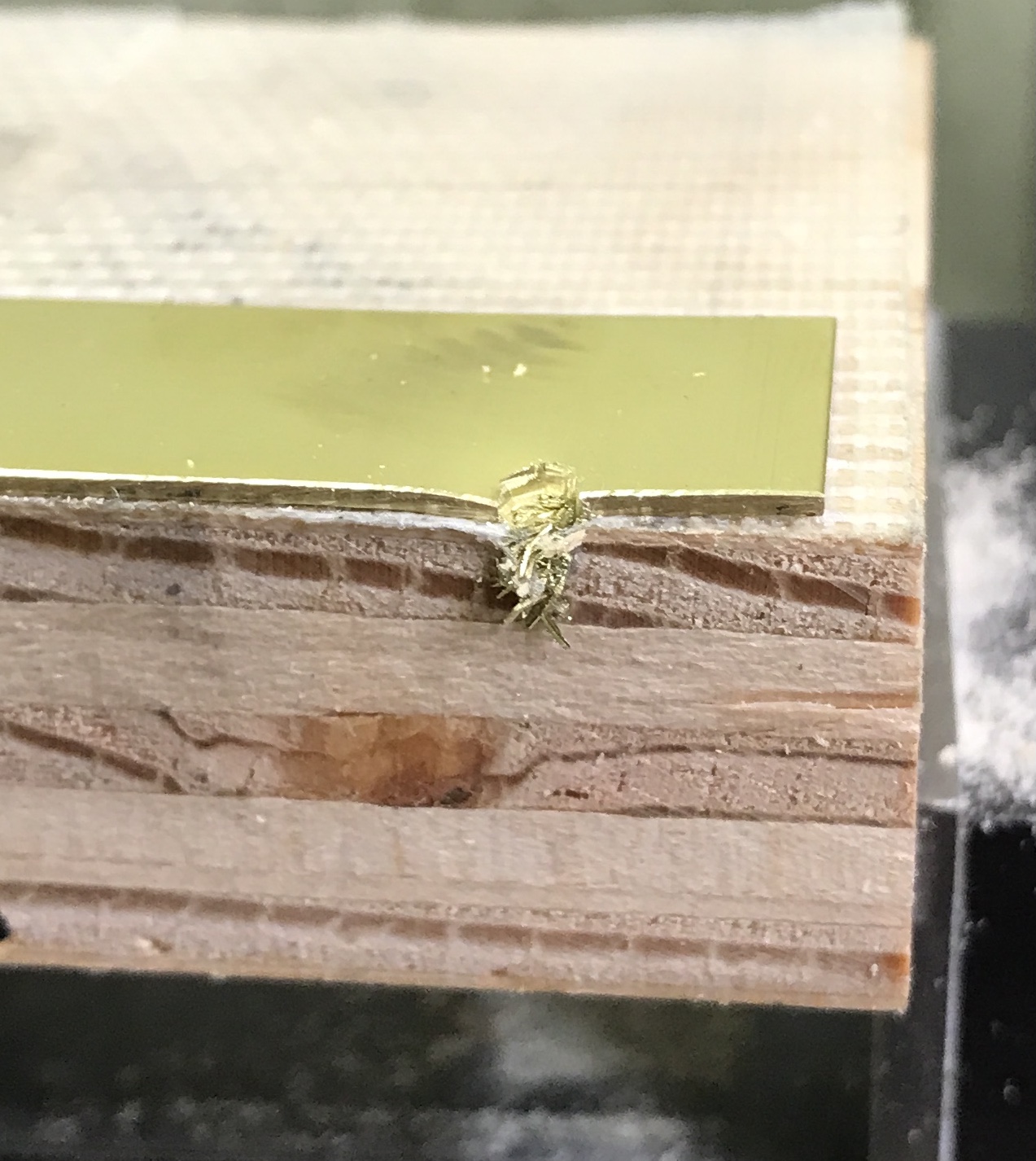
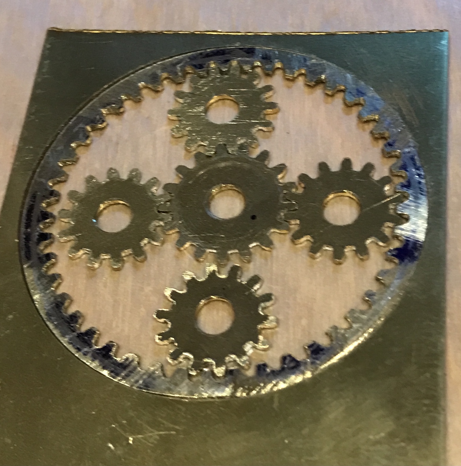
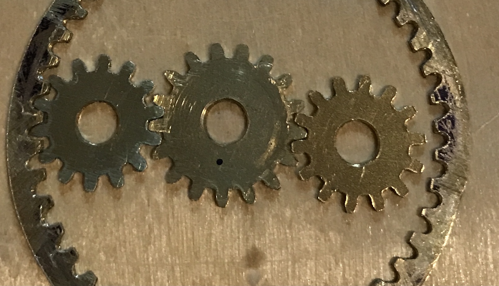
After a week at Perdido Key with Rhea and my sisters it is time to finish this business card. The next task is cutting the slots in the top of the card. Placing the gears in order to measure slot location, demonstrated that they are too small! The photo below shows the problem. Either the central gear or the planetary gears need to be larger. It is difficult to measure the needed correction, but it is slightly less than 1/16". The gap can be seen between the left planetary gear and the internal gear, as well as between the bottom planetary gear and the central gear.
The table with planned gear dimensions from above is reproduced below with an additional row, measured outer diameter (or inner diameter for the internal gear). The differences between measured and planned are minimal. For the time being I will assume that the problem arises from the internal gear being too large. Unfortunately, these dimensions don't tell me how much bigger the gears need to be cut. The central gear measures 0.500" to 0.505" between teeth. The same planetary gears measurement is 0.405" to 0.410". The tooth depth for the central gear is then (0.632 - 0.502)/2 = 0.065". The tooth depth for the planetary gears is (0.532 - 0.408)/2 = 0.062".
| Internal Gear | Planetary Gear | Central Gear | |
|---|---|---|---|
| Outer Diameter = (#T + 2)/DP | 1.567 | 0.533 | 0.633 |
| # Teeth | 45 | 14 | 17 |
| Diametral Pitch | 30 | 30 | 30 |
| Pitch Diameter | 1.500 | 0.467 | 0.567 |
| Dedendum = 1.25/DP | 0.042 | 0.042 | 0.042 |
| Addendum = 1.0/DP | 0.034 | 0.034 | 0.034 |
| Measured OD/ID | 1.541 | 0.532 | 0.632 |
An estimate is that the central gear needs to be 0.050" larger in diameter. An OD of 0.683" with a diametral pitch of 30 implies 18.5 teeth. Either an OD of 0.667" or 0.700" provides 18 or 19 teeth, respectively. The PD for an 18 tooth gear is 0.600". On the other hand remaking the planetary gears requires a 15 tooth gear. Its OD is 0.567" and its PD is 0.500". Of course this is doubled and the total PD for the 3 gears is 1.567". The overall size of the current 3 gears when fully engaged is 1.537". This is just about the same size as the ID of the internal gear, no wonder there is no overlap! The photo shows the internal, central, and two planetary gears fully engaged. Quite the gap. The gap will easily accomodate 1/16" of increase. Time to make larger planetary gears.
| Planetary Gear | |
|---|---|
| Outer Diameter = (#T + 2)/DP | 0.567 |
| # Teeth | 15 |
| Diametral Pitch | 30 |
| Pitch Diameter | 0.500 |
The table above shows the final specs for the new planetary gears. Five new "squares" of 1/32" brass were cut out with a hacksaw. The squares were approximately 11/16" on a side. The center of each blank was marked as seen in the first photo below. The centers were punched and drilled with a center drill and a #19 drill. Burrs were removed. The blanks were placed on the mandrel and held tight with a nut, second photo below. Part way through reducing the squares to circles the nut came loose. The threads were shot, so the mandrel had to be partly remade.
The old screw was cut off of the mandrel with a hacksaw. The end was faced and 3/8" was reduced to 0.165". The end was chamfered and the shaft was threaded 8-32. The shaft end was center drilled for a tailstock center. The squares were returned to this new shaft and two nuts were used to hold the blanks in place. The blanks were turned to circles in increments of 0.005" and then reduced to 0.567" diameter. The lathe chuck was transferred to the Sherline gear cutting attachment on the mill. The spindle was lowered until the 30 DP #7 cutter just touched the top of the blanks.
The spindle was lowered half of the 0.215" thickness of the cutter. Then it was lowered half of the diameter of the blanks, 0.284". The spindle was locked. The cutter was advanced until it touched off on the blanks. A cutting chart was constructed with the LibreOffice template, Documents/Metalworking/Gear Cutting/Gear Cutting Measurements.ods. The gaps need to be cut 0.072" deep.
The teeth were cut with multiple issues along the way. They are not perfect but not bad considering. They were removed from the mandrel and separated with gentle hammering. Both sides were filed flat to remove the burrs. They were fit into the internal gear. The fit is tight. The internal gear gaps are probably not deep enough. We are one step closer to completion.
The internal gear gaps were deepened using the Dremel equipped with a diamond burr. The teeth were also thinned as needed and straightened with hand filing. The assembly of gears now seems to work, though it is difficult to really test it without a top to hold everything together.
The first attempt was made to cut the observation windows in the top sheet. A center punch was made in this sheet 1" from the end and centered across the 2" dimension. Four circles were scribed at radii: 0.219", 0.490", 0.667", & 0.854". The rotary table was centered on the milling table under the spindle. The brass sheet was taped to a block of similarly sized plywood. This was centered under the spindle using the slip-on-spud.
The table was moved 0.219 + 0.0625". The table was rotated to 7°. A hole was drilled with the center drill and then with a 1/8" drill. The drill was switched for a 1/8" end mill. The curve was milled to 52°. This is when I realized I made a mistake. The plan is to cut the curves between the following angles: 7 - 52°, 67 - 112°, 127 - 172°, 187 - 232°, 247 - 292°, & 307 - 352°. The rotation needs to start after 7° and stop before 52° to keep the cut inside these bounds. I need to do some math to figure out the correct angular bounds of these circles.
The math was simple. The circumference of the smallest circle is 1.769". Half of the diameter of the drill is 3.5% of the circumference. This corresponds to 12.7° for this circle. Consequently, the limiting angles for the first arc are 20° and 39°. The other four arcs are limited by the following angle pairs: 80 - 99°, 140 - 159°, 200 - 219°, 260 - 279°, & 320 - 339°.
The layout was repeated on a second similarly sized piece of brass. This brass stock was carpet taped to the wooden block and centered under the spindle after recentering the rotary table. The table was set to 0° and locked. The y-axis was shifted 0.219 + 0.0625" putting the spindle inside the first line. A hole was drilled with a center drill followed by a 1/8" drill. The drill chuck was switched for a 1/8" end mill. This was lowered past the depth of the 1/32" thick brass stock. The table was turned to 19° while cutting. The end mill was raised and the table turned to 60°. The drill chuck was returned to the spindle and a second hole was drilled. Back to the end mill and the brass was cut to 79°. This was repeated for the following angles: 120 - 139°, 180 - 199°, 240 - 259°, & 300 - 319°.
The table was at 319°. The rotary table was locked and a slot was cut 0.146" (0.49-.282-.0625) away from the center of the circle. The y-axis was locked, the rotary table unlocked, and an arc was cut back to 300°. After locking the rotary table and unlocking the y-axis the opening was cut back toward center, 0.146". This process was repeated for the remaining five openings. The six openings at this stage are seen in the photo below.
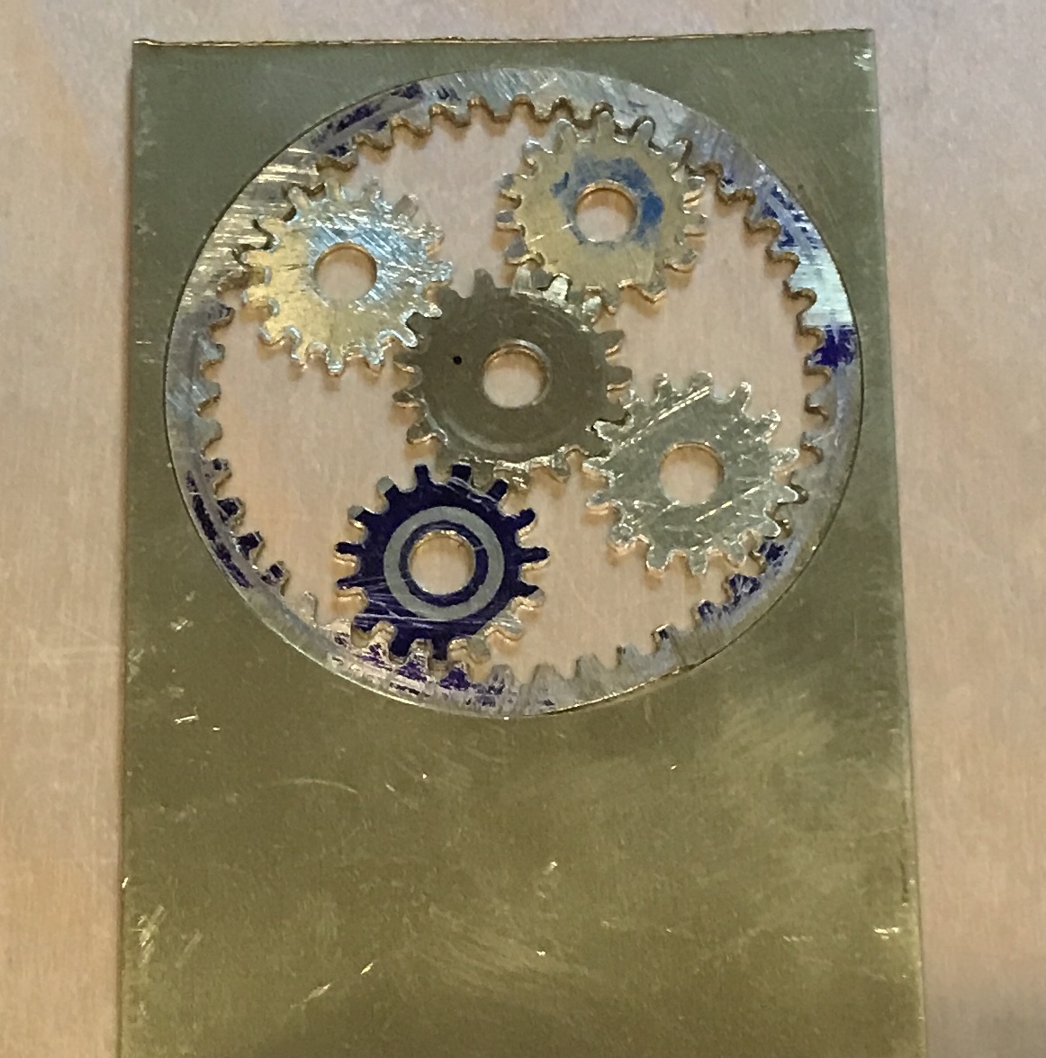
The six outside windows will be cut with the same angular limits. The table needs to be moved 0.448" to put the spindle 1/16" outside the third ring. This was done. With the table at 0° the first hole was drilled. This time the full opening was cut before moving on. The table was moved 0.08" between rings. The final six openings are shown below. After a little work with a file the windows were placed over the assembled gears. The revealed gears are seen in the second photo.
Looking back at the original plans, a discrepancy was discovered. The outer openings are narrower than planned. Using the same angular limits for inner and outer was not the correct way to proceed. I can either stick with what I have, open these up, or cut a new top card face.